In Printed Circuit Board design, Fiducial marks are used to align the pick and place machine with the PCB. A fiducial requires a circular area free of silkscreen and solderpaste, and in the middle of that area is a smaller circle exposing the top metal of the PCB.
Creating these in Altium with keepouts can be problematic because it will create a keepout on both layers when typically you only want the keepout on the same layer as the fiducial.
I recently saw a great solution for this: do it with a clearance rule. Create a Clearance design rule named "FiducialClearance" (or whatever you want to name it) that specifies the 26mil clearance
needed and is limited to just your fiducials. Create a new rule with the following:
HasFootprint('Fiducial-40mil')
Obviously, replace 'Fiducial-40mil' with the name of your fiducial footprint.
Finally change the priority of the "FiducialClearance" rule so that Priority=1.
Wednesday, March 4, 2015
Thursday, October 16, 2014
The Difference Between an Amateur Engineer and a Professional Engineer
An amateur grabs any old part from the parts bin and puts it into the board. A professional only uses parts that he has a valid part number for, since it will need to go into documentation somewhere.
An amateur assembles boards themselves. A professional only hand-builds if it will save money.
An amateur stores board revisions in zip files. A professional uses version control (like SVN).
An amateur doesn't pay attention to ESD when reworking boards. A professional uses proper grounding & wrist strap.
An amateur tries to solve all the problems himself. A professional coerces the manufacturer to help. :)
An amateur tests whether a design works. A professional tests how well the design works.
An amateur cares about the cost of the software tool. A professional cares about the productivity of the tool.
An amateur asks a question on a forum without RTFM. A professional asks a question on a forum after RTFM, usually when the documentation contradicts itself. :)
An amateur doesn't care about software licensing. A professional can tell you when you can use GPL code vs. LGPL vs. BSD license.
Friday, September 26, 2014
Demystifying Decoupling Capacitor Placement
Digital ICs require decoupling capacitors, to absorb the small current spikes from the switching behavior of the IC. Most of what we know about decoupling capacitor layout is "conventional wisdom", such as:
1. Need a variety of capacitance values to decouple a wide frequency range
2. Many capacitors of one value is better than many values
3. Place caps close to ICs
4. Location doesn't matter
5. Spread caps across the entire board
Most of our conventional wisdom is based on guidelines instead of empirical data.
I found an excellent presentation which explains proper decoupling capacitor placement:
https://ewh.ieee.org/r3/enc/emcs/archive/2012-10-10b_DecouplingMyths.pdf
1. Need a variety of capacitance values to decouple a wide frequency range
2. Many capacitors of one value is better than many values
3. Place caps close to ICs
4. Location doesn't matter
5. Spread caps across the entire board
Most of our conventional wisdom is based on guidelines instead of empirical data.
I found an excellent presentation which explains proper decoupling capacitor placement:
https://ewh.ieee.org/r3/enc/emcs/archive/2012-10-10b_DecouplingMyths.pdf
Friday, August 1, 2014
Using Texas Instruments Tiva Microcontroller Temperature Sensor
The Tiva line of processors from Texas Instruments has an internal temperature sensor. Code to do this is below. To use this,
/**
* Tiva Microcontroller Internal Temperature Utility Functions
*
* @section license License
* This work is PUBLIC DOMAIN
*
* YOU FURTHER ACKNOWLEDGE AND AGREE THAT THE SOFTWARE AND DOCUMENTATION ARE PROVIDED “AS IS”
* WITHOUT WARRANTY OF ANY KIND, EITHER EXPRESS OR IMPLIED, INCLUDING WITHOUT LIMITATION, ANY
* WARRANTY OF MERCHANTABILITY, TITLE, NON-INFRINGEMENT AND FITNESS FOR A PARTICULAR PURPOSE. IN NO
* EVENT SHALL TESLA CONTROLS BE LIABLE OR OBLIGATED UNDER CONTRACT, NEGLIGENCE,
* STRICT LIABILITY, CONTRIBUTION, BREACH OF WARRANTY, OR OTHER LEGAL EQUITABLE THEORY ANY DIRECT OR
* INDIRECT DAMAGES OR EXPENSE INCLUDING BUT NOT LIMITED TO ANY INCIDENTAL, SPECIAL, INDIRECT,
* PUNITIVE OR CONSEQUENTIAL DAMAGES, LOST PROFITS OR LOST DATA, COST OF PROCUREMENT OF SUBSTITUTE
* GOODS, TECHNOLOGY, SERVICES, OR ANY CLAIMS BY THIRD PARTIES (INCLUDING BUT NOT LIMITED TO ANY
* DEFENSE THEREOF), OR OTHER SIMILAR COSTS.
*/
/**
* Initialize the ADC for use by the temperature sensor.
* @see TivaWare/examples/peripherals/adc/temperature_sensor.c
* @post temperature sensor can be read with halGetTemperature()
*/
static void halTemperatureSensorInit()
{
/** Enable the ADC */
SysCtlPeripheralEnable(SYSCTL_PERIPH_ADC0);
#define ADC_SEQUENCE 3
#define ADC_STEP 0
/* Enable sample sequence 3 with a processor signal trigger.
* Sequence 3 will do a single sample when the processor sends a signal to start the conversion. */
ADCSequenceConfigure(ADC0_BASE, ADC_SEQUENCE, ADC_TRIGGER_PROCESSOR, 0);
/* Configure step 0 on sequence 3:
* - Sample the temperature sensor (ADC_CTL_TS) in single-ended mode (default)
* - Configure the interrupt flag (ADC_CTL_IE) to be set when the sample is done
* - Tell the ADC logic that this is the last conversion on sequence 3 (ADC_CTL_END). */
ADCSequenceStepConfigure(ADC0_BASE, ADC_SEQUENCE, ADC_STEP, ADC_CTL_TS | ADC_CTL_IE | ADC_CTL_END);
/* Enable the ADC Sequence we're using */
ADCSequenceEnable(ADC0_BASE, ADC_SEQUENCE);
/* Clear the interrupt status flag. This is done to make sure the interrupt flag is cleared before we sample. */
ADCIntClear(ADC0_BASE, ADC_SEQUENCE);
}
/**
* Read the processor's internal temperature sensor. Accuracy is +/-5C
* @pre halTemperatureSensorInit() was called to initialize the ADC
* @return temperature of processor in degrees Celsius
* @note to convert: VTSENS = 2.7 - ((TEMP + 55) / 75)
*/
int32_t halGetTemperature()
{
/* This array is used for storing the data read from the ADC FIFO. It must be as large as the
FIFO for the sequencer in use. This example uses sequence 3 which has a FIFO depth of 1. */
uint32_t ulADC0_Value[1];
/* Our output value */
int32_t temperatureInDegreesC;
/* Manually Trigger the ADC conversion */
ADCProcessorTrigger(ADC0_BASE, 3);
/* Wait for conversion to be completed */
while(!ADCIntStatus(ADC0_BASE, 3, false))
{
}
/* Clear the ADC interrupt flag. */
ADCIntClear(ADC0_BASE, 3);
/* Read ADC Value. */
ADCSequenceDataGet(ADC0_BASE, 3, ulADC0_Value);
//UARTprintf("ADC Value = %u\n", ulADC0_Value[0]);
/* Reference voltage of 3.3V, in mV. */
#define REFERENCE_VOLTAGE_MV (3300l)
/* ADC is 12 bit resolution */
#define NUMBER_OF_STEPS_12_BIT_RESOLUTION (4096l)
/* The voltage from the ADC, in millivolts */
uint32_t adcMv = (uint32_t) ((ulADC0_Value[0] * REFERENCE_VOLTAGE_MV) / NUMBER_OF_STEPS_12_BIT_RESOLUTION);
/* Use non-calibrated conversion provided in the data sheet. Divide last to avoid dropout. */
temperatureInDegreesC = (147500l - 75l * adcMv) / 1000;
return temperatureInDegreesC;
}
/**
* Utility function to convert a celsius temperature to fahrenheit.
* @param temperatureInDegreesC the temp in C
* @return the temp in F
*/
int32_t halConvertTemperatureFromCtoF(int32_t temperatureInDegreesC)
{
return ((temperatureInDegreesC * 9) + 160) / 5;
}
- Call halTemperatureSensorInit() to initialize the sensor and ADC. Only needs to be done once.
- Call halGetTemperature() to get the temperature in Celsius
- Optionally, call halConvertTemperatureFromCtoF to convert it to Fahrenheit
/**
* Tiva Microcontroller Internal Temperature Utility Functions
*
* @section license License
* This work is PUBLIC DOMAIN
*
* YOU FURTHER ACKNOWLEDGE AND AGREE THAT THE SOFTWARE AND DOCUMENTATION ARE PROVIDED “AS IS”
* WITHOUT WARRANTY OF ANY KIND, EITHER EXPRESS OR IMPLIED, INCLUDING WITHOUT LIMITATION, ANY
* WARRANTY OF MERCHANTABILITY, TITLE, NON-INFRINGEMENT AND FITNESS FOR A PARTICULAR PURPOSE. IN NO
* EVENT SHALL TESLA CONTROLS BE LIABLE OR OBLIGATED UNDER CONTRACT, NEGLIGENCE,
* STRICT LIABILITY, CONTRIBUTION, BREACH OF WARRANTY, OR OTHER LEGAL EQUITABLE THEORY ANY DIRECT OR
* INDIRECT DAMAGES OR EXPENSE INCLUDING BUT NOT LIMITED TO ANY INCIDENTAL, SPECIAL, INDIRECT,
* PUNITIVE OR CONSEQUENTIAL DAMAGES, LOST PROFITS OR LOST DATA, COST OF PROCUREMENT OF SUBSTITUTE
* GOODS, TECHNOLOGY, SERVICES, OR ANY CLAIMS BY THIRD PARTIES (INCLUDING BUT NOT LIMITED TO ANY
* DEFENSE THEREOF), OR OTHER SIMILAR COSTS.
*/
/**
* Initialize the ADC for use by the temperature sensor.
* @see TivaWare/examples/peripherals/adc/temperature_sensor.c
* @post temperature sensor can be read with halGetTemperature()
*/
static void halTemperatureSensorInit()
{
/** Enable the ADC */
SysCtlPeripheralEnable(SYSCTL_PERIPH_ADC0);
#define ADC_SEQUENCE 3
#define ADC_STEP 0
/* Enable sample sequence 3 with a processor signal trigger.
* Sequence 3 will do a single sample when the processor sends a signal to start the conversion. */
ADCSequenceConfigure(ADC0_BASE, ADC_SEQUENCE, ADC_TRIGGER_PROCESSOR, 0);
/* Configure step 0 on sequence 3:
* - Sample the temperature sensor (ADC_CTL_TS) in single-ended mode (default)
* - Configure the interrupt flag (ADC_CTL_IE) to be set when the sample is done
* - Tell the ADC logic that this is the last conversion on sequence 3 (ADC_CTL_END). */
ADCSequenceStepConfigure(ADC0_BASE, ADC_SEQUENCE, ADC_STEP, ADC_CTL_TS | ADC_CTL_IE | ADC_CTL_END);
/* Enable the ADC Sequence we're using */
ADCSequenceEnable(ADC0_BASE, ADC_SEQUENCE);
/* Clear the interrupt status flag. This is done to make sure the interrupt flag is cleared before we sample. */
ADCIntClear(ADC0_BASE, ADC_SEQUENCE);
}
/**
* Read the processor's internal temperature sensor. Accuracy is +/-5C
* @pre halTemperatureSensorInit() was called to initialize the ADC
* @return temperature of processor in degrees Celsius
* @note to convert: VTSENS = 2.7 - ((TEMP + 55) / 75)
*/
int32_t halGetTemperature()
{
/* This array is used for storing the data read from the ADC FIFO. It must be as large as the
FIFO for the sequencer in use. This example uses sequence 3 which has a FIFO depth of 1. */
uint32_t ulADC0_Value[1];
/* Our output value */
int32_t temperatureInDegreesC;
/* Manually Trigger the ADC conversion */
ADCProcessorTrigger(ADC0_BASE, 3);
/* Wait for conversion to be completed */
while(!ADCIntStatus(ADC0_BASE, 3, false))
{
}
/* Clear the ADC interrupt flag. */
ADCIntClear(ADC0_BASE, 3);
/* Read ADC Value. */
ADCSequenceDataGet(ADC0_BASE, 3, ulADC0_Value);
//UARTprintf("ADC Value = %u\n", ulADC0_Value[0]);
/* Reference voltage of 3.3V, in mV. */
#define REFERENCE_VOLTAGE_MV (3300l)
/* ADC is 12 bit resolution */
#define NUMBER_OF_STEPS_12_BIT_RESOLUTION (4096l)
/* The voltage from the ADC, in millivolts */
uint32_t adcMv = (uint32_t) ((ulADC0_Value[0] * REFERENCE_VOLTAGE_MV) / NUMBER_OF_STEPS_12_BIT_RESOLUTION);
/* Use non-calibrated conversion provided in the data sheet. Divide last to avoid dropout. */
temperatureInDegreesC = (147500l - 75l * adcMv) / 1000;
return temperatureInDegreesC;
}
/**
* Utility function to convert a celsius temperature to fahrenheit.
* @param temperatureInDegreesC the temp in C
* @return the temp in F
*/
int32_t halConvertTemperatureFromCtoF(int32_t temperatureInDegreesC)
{
return ((temperatureInDegreesC * 9) + 160) / 5;
}
Thursday, May 8, 2014
The Main Event - A Simple Event Handler for Microcontrollers
Every application has some type of event handler. Typically, an interrupt will occur, and the interrupt service routine (ISR) will then set a flag, and then the ISR will exit to return to the normal application. This approach is used to minimize the time spent in the ISR. Next, in the main application, the event flags are read, and if any were set then the application processes each event.
I've been looking through the Anaren Bluetooth Low Energy software lately, and I saw this rather cool event handler. It uses a table of function pointers that are the functions to be called when the event occurs.
/* Typedef for the event handler functions that will go into our table */
typedef void (*Hal_Handler)(void);
Next, for convenience we also create a type for the event flag bitmask. For speed, make this the same as the processor's data size.
/* The type of integer that we will use for our event bitflag. uint32 = 32 possible events */
typedef uint32_t EventFlags;
We also create the global variable that will be the bitflag of any events that get set.
/* Bitflag of the events that need to be processed */
static volatile EventFlags handlerEvents = 0;
To complete the initialization, we define a few events, and create our event handler table.
#define NUM_HANDLERS 3
#define BUTTON_HANDLER_ID 0
#define TICK_HANDLER_ID 1
#define DISPATCH_HANDLER_ID 2
#define KNOB_INCREMENT_HANDLER_ID 3
#define KNOB_DECREMENT_HANDLER_ID 4
/* Table of handler function pointers */
static Event_Handler handlerTable[NUM_HANDLERS];
This table will contain function pointers for the function that gets called when the corresponding event gets called. For example, when the knob gets rotated clockwise, its ISR will set bit #3 in the handlerEvents function. Then the main loop will call the function that is located at handlerTable[3].
We initialize our list by adding event handlers to the event handler table using the method below:
int addEventHandler(uint8_t index, Event_Handler handler)
{
if (index > NUM_HANDLERS)
{
return -1;
}
handlerTable[index] = handler;
return 0;
}
We then call this in our main() function, which we'll explain in a bit.
/** Set the corresponding bitflag for the eventId */
void postEvent(uint8_t handlerId)
{
//Note: you should check that handlerId < NUM_HANDLERS here
IntMasterDisable();
handlerEvents |= 1 << handlerId;
IntMasterEnable();
}
In the ISRs, you will need to add a call to postEvent. For example, in a button ISR, add:
postEvent(BUTTON_HANDLER_ID);
void buttonHandler(void)
{
printf("Button Pressed!\r\n");
}
void knobIncrementHandler(void)
{
printf("Knob Up!\r\n");
}
void knobDecrementHandler(void)
{
printf("Knob Down!\r\n");
}
Now, we need these in the Event Table so in main() we add them with the function we created earlier:
addEventHandler(BUTTON_HANDLER_ID, buttonHandler);
addEventHandler(KNOB_INCREMENT_HANDLER_ID, knobIncrementHandler);
addEventHandler(KNOB_DECREMENT_HANDLER_ID, knobDecrementHandler);
Now we've configured the event setting, and the event processing, so now we can implement the main event handler.
void eventHandler(void)
{
IntMasterEnable();
for (;;)
{
/* First, disable interrupts so we don't get messed up while we are reading events */
IntMasterDisable();
/* While interrupts are disabled, copy the current list of events that need to be processed */
EventFlags events = handlerEvents;
/* ... and clear the master bitflag of events */
handlerEvents = 0;
/* Now, process any events that need to be processed */
if (events)
{ // dispatch all current events
IntMasterEnable(); // Enable interrupts - note that we do this before calling each handler function
/* mask will be the bitflag that we use to check the events bitflag. Starts at 0x1, then 0x2, 0x4, 0x8 etc. */
uint16_t mask;
/* The numeric index of the event - 0 through 31 */
uint8_t id;
/** Iterate through all possible events */
for (id = 0, mask = 0x1; id < NUM_HANDLERS; id++, mask <<= 1)
{
if ((events & mask) && handlerTable[id]) // If we need to process the event
{ // AND there is an event handler for it
handlerTable[id](); // ... Then process the event
}
}
} else { // No events to handle, so wait for more
/* If using a battery powered device, you could go back to sleep here. Just be sure to enable interrupts! */
IntMasterEnable(); // Enable Interrupts
}
}
}
I've been looking through the Anaren Bluetooth Low Energy software lately, and I saw this rather cool event handler. It uses a table of function pointers that are the functions to be called when the event occurs.
The Event Handler Functions
We will create a typedef for our function pointer. All functions in our Event Handler Table need to be this type./* Typedef for the event handler functions that will go into our table */
typedef void (*Hal_Handler)(void);
Next, for convenience we also create a type for the event flag bitmask. For speed, make this the same as the processor's data size.
/* The type of integer that we will use for our event bitflag. uint32 = 32 possible events */
typedef uint32_t EventFlags;
We also create the global variable that will be the bitflag of any events that get set.
/* Bitflag of the events that need to be processed */
static volatile EventFlags handlerEvents = 0;
To complete the initialization, we define a few events, and create our event handler table.
#define NUM_HANDLERS 3
#define BUTTON_HANDLER_ID 0
#define TICK_HANDLER_ID 1
#define DISPATCH_HANDLER_ID 2
#define KNOB_INCREMENT_HANDLER_ID 3
#define KNOB_DECREMENT_HANDLER_ID 4
/* Table of handler function pointers */
static Event_Handler handlerTable[NUM_HANDLERS];
This table will contain function pointers for the function that gets called when the corresponding event gets called. For example, when the knob gets rotated clockwise, its ISR will set bit #3 in the handlerEvents function. Then the main loop will call the function that is located at handlerTable[3].
We initialize our list by adding event handlers to the event handler table using the method below:
int addEventHandler(uint8_t index, Event_Handler handler)
{
if (index > NUM_HANDLERS)
{
return -1;
}
handlerTable[index] = handler;
return 0;
}
We then call this in our main() function, which we'll explain in a bit.
Set a flag when an event occurs
When an event happens, in the ISR we need to set the bitflag that corresponds to that event. This is done in the postEvent() method as shown below. This bitflag will be read later in our main event handling loop. For safety, we disable interrupts while we are modifying the handlerEvents variable./** Set the corresponding bitflag for the eventId */
void postEvent(uint8_t handlerId)
{
//Note: you should check that handlerId < NUM_HANDLERS here
IntMasterDisable();
handlerEvents |= 1 << handlerId;
IntMasterEnable();
}
In the ISRs, you will need to add a call to postEvent. For example, in a button ISR, add:
postEvent(BUTTON_HANDLER_ID);
Configuring The Actions
When the bitflag for an event gets set, we want the event handler to do something. It does so by calling a function pointer that points to the function that we want to get called when that event happens. For example, when a button is pressed we just want to tell the user. Same for knob, as shown below:void buttonHandler(void)
{
printf("Button Pressed!\r\n");
}
void knobIncrementHandler(void)
{
printf("Knob Up!\r\n");
}
void knobDecrementHandler(void)
{
printf("Knob Down!\r\n");
}
Now, we need these in the Event Table so in main() we add them with the function we created earlier:
addEventHandler(BUTTON_HANDLER_ID, buttonHandler);
addEventHandler(KNOB_INCREMENT_HANDLER_ID, knobIncrementHandler);
addEventHandler(KNOB_DECREMENT_HANDLER_ID, knobDecrementHandler);
Now we've configured the event setting, and the event processing, so now we can implement the main event handler.
The Main Event (handler)
The Main Event Handler is fairly simple. It continually loops, and processes any events that were set by postEvent(). If a bitflag was set, then it calls the corresponding function pointer.void eventHandler(void)
{
IntMasterEnable();
for (;;)
{
/* First, disable interrupts so we don't get messed up while we are reading events */
IntMasterDisable();
/* While interrupts are disabled, copy the current list of events that need to be processed */
EventFlags events = handlerEvents;
/* ... and clear the master bitflag of events */
handlerEvents = 0;
/* Now, process any events that need to be processed */
if (events)
{ // dispatch all current events
IntMasterEnable(); // Enable interrupts - note that we do this before calling each handler function
/* mask will be the bitflag that we use to check the events bitflag. Starts at 0x1, then 0x2, 0x4, 0x8 etc. */
uint16_t mask;
/* The numeric index of the event - 0 through 31 */
uint8_t id;
/** Iterate through all possible events */
for (id = 0, mask = 0x1; id < NUM_HANDLERS; id++, mask <<= 1)
{
if ((events & mask) && handlerTable[id]) // If we need to process the event
{ // AND there is an event handler for it
handlerTable[id](); // ... Then process the event
}
}
} else { // No events to handle, so wait for more
/* If using a battery powered device, you could go back to sleep here. Just be sure to enable interrupts! */
IntMasterEnable(); // Enable Interrupts
}
}
}
Friday, May 2, 2014
Using Bluetooth Low Energy to Do Something
In the previous post we looked at how to get up and running with Bluetooth Low Energy. Now we're going to do something useful. This section assumes that you have completed the previous tutorial successfully.
Load on-line Help
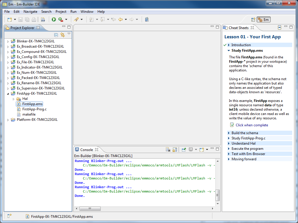
First, we want to load the on-line help for the FirstApp example. Open Em-Builder and select Help > Em-Builder > Primer Contents and you'll see a number of lessons available:Select "Lesson 01 - Your First App" and the workspace will change to load the on-line help:
Run Unmodified FirstApp
Just like you did for Blinker, now right-click on the FirstApp project in the left hand column and select "Run Em-Builder Example". If you had an error, be sure that your development board is attached, and try the Em-blinker example too. Now open Em-Browser on your iPhone and connect to your development board. You should be able to read and write a variable with the unoriginal name of "data". Fun.Customizing FirstApp
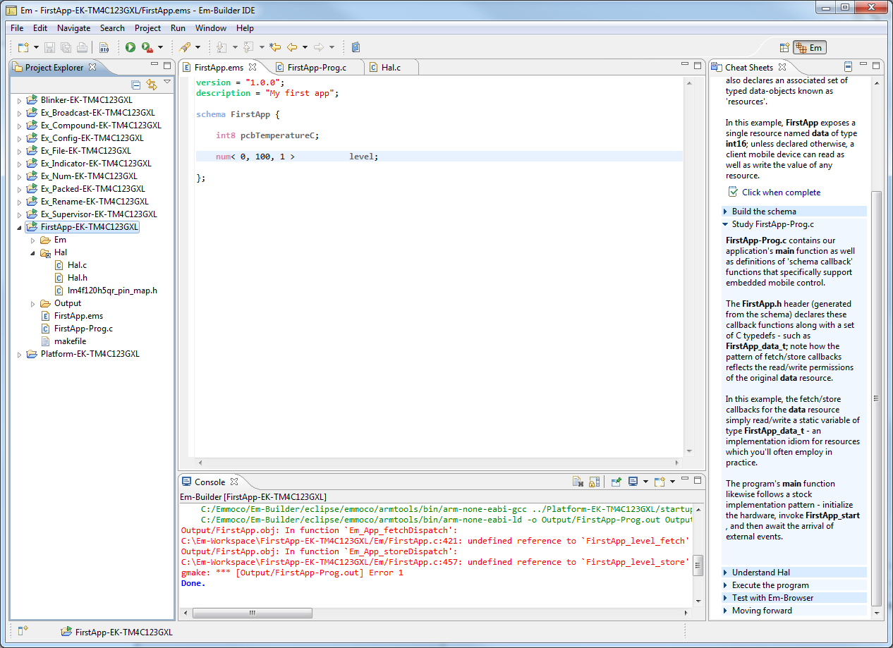
The first thing that we're going to do to get our feet wet with the Emmoco software is to do something very simple: change the name of the "data" variable to "pcbTemperature". This will give us a good exposure to what Emmoco uses to communicate. Make the change in the schema, FirstApp.ems.If you try to build it, then you will get an error, complaining of an unknown type name.
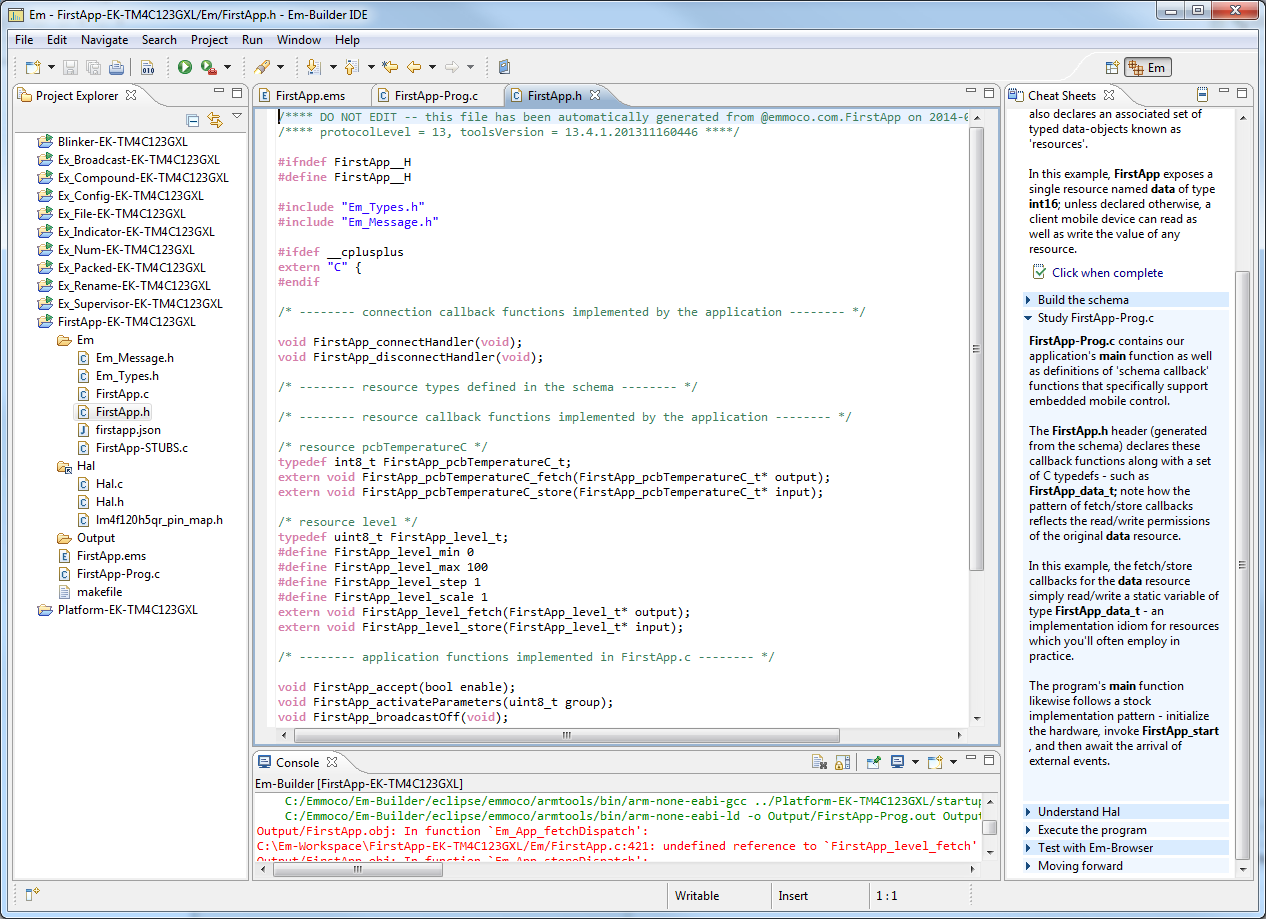
Now in the schema (FirstApp.ems) change the name of the variable "data". This will cause the build to fail, because we need to change all the other variables. If you go to FirstApp.h then you can see declarations of the new typedef and functions.
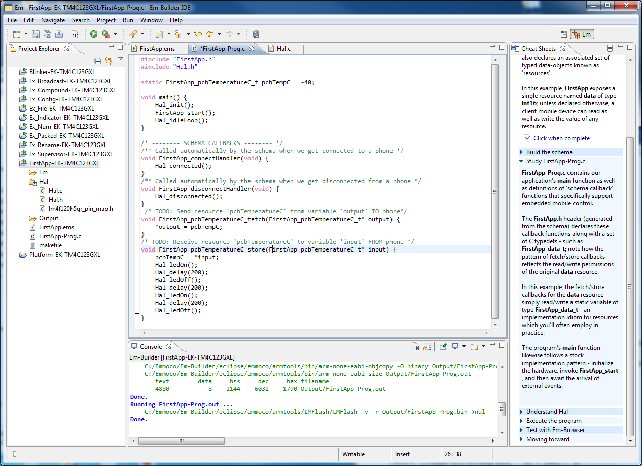
Now, make these changes to FirstApp.c
Now that we've renamed the variables, we should be able to build successfully. Run the example (Right-click on project and select "Run Em-Builder Example") and it will be loaded on the development board. Using Em-Browser you should be able to read and write a resource named pcbTemperature.
Do Something When We Receive a New Value
Ok, now we're rolling.Now, just for fun, we modify the function pcbTemperatureC_store() as shown below to blink LED twice whenever we get a new value.
Now, in Em-Browser, write a value to pcbTemperature and you'll see the LED blink twice. Cool! Too bad we don't have printf() here though; it would be nice to be able to see it.
Adding Another Variable
Now we want to add another variable. I looked through the schema examples and saw that there's a 'num' type where you can set the range and interval. This is useful so that the phone application will only send us valid values. We want to control a light, so we add a variable, called 'level'. This can vary between 0% (totally off) and 100% (totally on), in steps of 1 percent each.Now right click on the project and select"Build Project". It will report a few errors but more importantly it will automatically generate the typedefs and function declarations that we need. This will make our lives easier.
Here we can see that the Emmoco framework created a bunch of new stuff for us, including the following.
The min, max, step, and scale values are there because in the schema we defined our variable as a number with range of 0 to 100 and in steps of 1. We can copy/paste the function declarations into our application to make life easier. Now we need to add these to our application.
In FirstApp-Prog.c, add a variable:
static FirstApp_level_t intensity = 10;
Also add two new functions:
/* Send resource TO phone */
void FirstApp_level_fetch(FirstApp_level_t* output)
{
*output = intensity;
}
/* Receive new value FROM phone */
void FirstApp_level_store(FirstApp_level_t* input)
{
intensity = *input;
}
Run the Example
Now, try building again - 'Run Em-Builder Example'. You shouldn't have any errors.Now open Em-Browser on the iPhone. You can now see that we have a new resource, called Level, and we can write to it and read it.
Clicking on 'level' shows us more information about it. Note that if you try to write a level above 100 then it will be limited to 100.
Conclusion
In this tutorial we demonstrated how to modify one of their examples to do something useful and how to add another variable.
Location:
San Diego, CA 92122, USA
Get Started with Bluetooth Low Energy
This tutorial will show you how to develop an application with Bluetooth Low Energy and do something useful. Going through all the steps in this post will take between
30-60 minutes, depending on if you run into any issues. Bluetooth Low Energy (aka BLE) is all the rage right now, and rightfully so, as it is an easy to use low power RF communications protocol. All the new iPhones and some Android phones incorporate a BLE radio, so you can now easily design RF peripherals to communicate with the iPhone.
I like to use a module for BLE because it is easier and less expensive for quantities less than 10k. For this post I'm trying out the Anaren BLE Module which is available on a Development kit from Digikey for $60. You will also need a Texas Instruments Launchpad. I'm using the TI Tiva Launchpad which available from Digikey for about $14. These are so cheap that I recommend buying two. Below is a picture of the Anaren Board mounted on the Tiva Development Board.
For this tutorial, you will need:
The Anaren module uses a framework from Emmoco to make development easier. Go to www.em-hub.com. You will need to create an account to be able to download the software. Click on the "Sign-Up" link. The access code that it wants is printed on a sticker on the Anaren board. It is on the black connector, on the far left of the above image. Enter that code and your other information. Next, click on the "Downloads" link and select v13, and then "Em-Builder IDE Container" for your operating system.
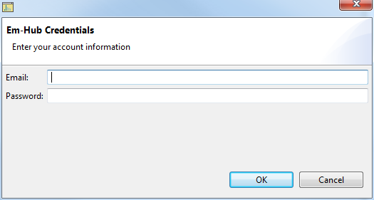
Now we'll follow along the instructions in the left pane. Select Help > Em-Builder > Em-Hub Credentials and enter the same username and password you used to create your account.
Once you have updated the firmware, it will be happy:
If you want, you can also change the name of the device here. Call it "SHAMU" or whatever you would like as long as it's all upper case. Now we're done updating the module firmware. If you want, you can remove the USB cable from the "ADMIN UART" port now.
Now, the application should have a few example projects:
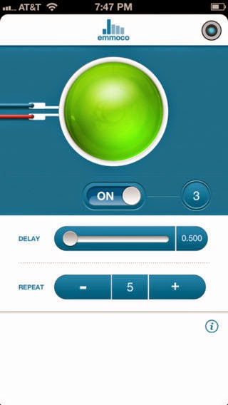
Now, open the "Em-Blinker" application on your phone. It should look something like below:
It doesn't do anything yet, you need to tell it to connect to your board. Press the button in the upper right corner to select the board. Previously we named our board "SHAMU" so we select that one. On the Tiva board, the Red LED should illuminate to indicate that it is connected to a phone.
Now, press "Start" or "On" depending on your version of Em-Blinker, and you should now see the blue LED on the Tiva board blink.
I like to use a module for BLE because it is easier and less expensive for quantities less than 10k. For this post I'm trying out the Anaren BLE Module which is available on a Development kit from Digikey for $60. You will also need a Texas Instruments Launchpad. I'm using the TI Tiva Launchpad which available from Digikey for about $14. These are so cheap that I recommend buying two. Below is a picture of the Anaren Board mounted on the Tiva Development Board.
For this tutorial, you will need:
- Anaren BLE Development Kit
- Mini-USB cable for above (comes with the kit)
- Texas Instruments Tiva Launchpad
- Micro-USB cable for above (comes with the kit)
- iPhone, 4S or later to run phone examples
- iPhone apps "Em-Blinker" & "Em-Browser", available for free from the App Store
- Basic knowledge of C
Hardware Connections
First, mate the two boards as shown above. Next, connect the Tiva's "Debug" USB port to your computer. Be sure that the slider switch is in the "DEBUG" position. Finally connect the "Admin UART" USB port on the Anaren Board to your computer.
Get the Software
Install the Software
After it downloads, install the software. It will also install some drivers too. When you first start the application it will look rather empty, like below.Now we'll follow along the instructions in the left pane. Select Help > Em-Builder > Em-Hub Credentials and enter the same username and password you used to create your account.
Update Development Board Firmware
Next, you'll connect to the board and update the firmware. The hardest part on this step is figuring out which serial port is used for the "UART-ADMIN" port. I tried each of them but figured out finally that it was COM75 on mine. If the application is showing an error, then one thing to try is to press the "MCU Reset SOC" button on the Anaren Board; that allowed the two devices to connect. This took me awhile to figure out.Once you have updated the firmware, it will be happy:
If you want, you can also change the name of the device here. Call it "SHAMU" or whatever you would like as long as it's all upper case. Now we're done updating the module firmware. If you want, you can remove the USB cable from the "ADMIN UART" port now.
Get the Example Projects
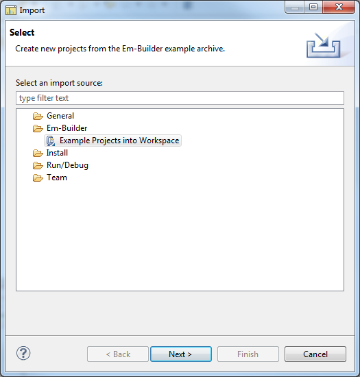
Now we need to import some examples so that we can start playing with them. GO to File > Import > Em-Builder > Example Projects, and select EK-TM4C123GXL as shown below.Now, the application should have a few example projects:
Running an Example Application
Now we are ready to do something useful. Be sure that the USB cable to the Tiva board is connected to your computer. Right-click on the "Blinker-EK-TM4C123GXL" example and select "Run Em-Builder Example". It should compile and build, as shown below.Now, open the "Em-Blinker" application on your phone. It should look something like below:

Now, press "Start" or "On" depending on your version of Em-Blinker, and you should now see the blue LED on the Tiva board blink.
Conclusion
In this tutorial we started from zero and ended with a phone connected to our embedded device. Next time we'll look at making our own application.
Location:
San Diego, CA 92122, USA
Wednesday, April 30, 2014
The Easy Way to Use Thermistors
A Thermistor is a resistor that varies its values with temperature. These are fairly inexpensive and easy to use with a microcontroller that has an analog to digital converter (ADC). However, figuring out how to compute the exact temperature is not simple. Here I go through the process that I use. I call it "The Easy Way" because I use Excel and Word to do the heavy lifting for me.
There are two types of thermistors, Negative Temperature Coefficient (NTC) and Positive Temperature Coefficient (PTC). Simply, for NTC thermistors, the resistance goes DOWN when the temperature goes UP.
In a circuit, thermistors are typically half of a voltage divider. In our example, the top half of the voltage divider is a 10k Ohm, 1% fixed resistor, powered by Vref, 2.5V. The bottom half of the voltage divider is a 10k Ohm 3% NTC thermistor.
Step 1: Get the temperature to resistance table
The math to convert from temperature to resistance is quite complex, so the manufacturers publish a table containing the resistance to temperature values. For example, see this link.Step 2: Get them into Excel
For the table in the previous link the values were in a PDF sheet. But we need them in Excel. If you have a lot of time on your hands then you can manually retype them all. But I'm lazy, so I did some creative cut/paste from the PDF file into a Notepad file. You need a table consisting of many rows, each row containing the Temperature (in C) and also the Resistance (in Ohms). In Excel I also added another column containing the temperature in degrees Fahrenheit. This is just for convenience and not used in any calculations. The equation to convert from C to F in excel is the following, assuming the value in C is in cell A24:
=CONVERT(A24, "C", "F")
Below we see what our table looks like after we have all our values. We only computed for the temperature range of 0C to 85C because that was our product requirements.
Step 3: Get your ADC working
Use an oscilloscope to measure the output voltage of the voltage divider, while also measuring with the ADC. This will help you calibrate your calculations. Be sure that you know the resolution of your ADC to get the corresponding maximum counts. For example, a 12 bit ADC has 4096 possible values. Obviously to be able to measure temperature you will need to measure the voltage output from the thermistor voltage divider.Step 4: Math Time
First, a few definitions:- R1 = our "top" resistor, in our case the fixed 10kOhm value
- Rt = the varying thermistor resistance
- Vref = the voltage supply to the top of the voltage divider, in our case 2.5V
- Vt = the output voltage of this voltage divider
Rt Vt
------- = ---------
(R1 +Rt) Vref
This can be rearranged to:
Rt = R1 / ( ( Vref/Vt) - 1)
Now, test this with your circuit, and verify that you are seeing reasonable values.Next, we need to convert this to ADC measurements. But first a couple more definitions:
- ADC= the value we measure from the ADC, in "counts"
- Resolution = The resolution of the ADC. In our case, this is 4096 because we have a 12-bit ADC.
Vt = (ADC / Resolution) * Vref
We can substitute this into the previous equation to get our magic equation:
ADC = (4096) / ( (R1/Rt) + 1)
Step 5: Make a Table
We can use this equation to create a table in Excel that contains the following tuplets:- Temperature (in C)
- Resistance (in Ohms)
- ADC Measurement
=((4096)/((10000/C22)+1))
However, this will give us decimal values. We want to round this off, so we use the following:
=ROUND(((4096)/((10000/C22)+1)), 0)
Below shows the table with the ADC values added:
Step 5: Convert this into a C Array
Here's where our laziness comes into play. We're going to use Microsoft Word to convert the list of values into a C array. First, select only the ADC column, starting at the value for 0C. Paste this as plain text into a new Microsoft Word file. Be sure to paste as plain text.Now we have a wonderful list of values. Next, use Word's find/replace option to replace the carriage return with a comma and a space, as shown below. Note the find string is "^p" without the quotes, and the replace string is ", " without the quotes.
This performs a bit of magic, turning our long list into something that's starting to look like an array:
Now, just wrap this with the variable definition and a comment explaining what it is, and we're done.
/** ADC values which correspond to temperature starting at 0C up to 85C*/
const uint16_t adcToTemperature[] = {3008, 2973, 2937, 2900, 2864, 2827, 2789, 2752,
2714, 2675, 2636, 2598, 2558, 2519, 2480, 2440, 2401, 2362, 2322, 2283, 2243, 2204,
2165, 2126, 2086, 2048, 2010, 1971, 1934, 1896, 1859, 1822, 1785, 1749, 1713, 1678,
1643, 1609, 1575, 1541, 1508, 1476, 1443, 1412, 1381, 1350, 1320, 1290, 1261, 1232,
1204, 1177, 1150, 1123, 1097, 1072, 1047, 1022, 998, 975, 952, 929, 907, 886, 865,
844, 824, 804, 785, 766, 748, 730, 712, 695, 679, 662, 646, 631, 616, 601, 587,
573, 559, 545, 532, 519};
Step 6: Get the Temperature for ADC Reading
We now have our array of values. To get the temperature we just iterate through this table, looking for the closest match. We're not doing any interpolation or anything fancy, just a straight look-up. If you need more accuracy then do something different./** Gets the temperature in degrees C for the specified ADC reading.
* @param adc the reading from the ADC
* @return the temperature in C, or ERROR_TEMPERATURE_NOT_FOUND if the value was not found.
*/
uint8_t getTemperatureForAdc(uint16_t adc)
{
#define ADC_RESOLUTION (4096)
if (adc > ADC_RESOLUTION)
{
return ERROR_TEMPERATURE_NOT_FOUND; //error - this should not happen
}
/* Now iterate through the table, looking for the nearest match */
uint32_t iterator = 0;
while (adc < adcToTemperature[iterator])
{
iterator++;
}
if (iterator == ADC_TO_TEMP_LOOKUP_TABLE_ROWS)
{
// We've gone through the entire table but haven't found a match
return ERROR_TEMPERATURE_NOT_FOUND; //error - this should not happen
}
return (iterator); // The temperature, in degrees C
}
Conclusion
We now have an easy and fast way to get the temperature from the thermistor.Thursday, September 12, 2013
Syntax Highlighting for Custom Keywords in IAR
Syntax highlighting makes code much easier to read by parsing the various elements (function names, parameters, constants, etc.) and displaying each differently. Unfortunately IAR doesn't recognize the C99 Fixed-Width Integer Types so it doesn't display them. For example see below. IAR doesn't display uint8_t any differently from the rest of the text.
To make IAR aware of these, you'll need to first create a custom keyword file, and then tell IAR to use it.
int8_t int16_t int32_t int64_t
int_fast8_t int_fast16_t int_fast32_t int_fast64_t
int_least8_t int_least16_t int_least32_t int_least64_t
uint8_t uint16_t uint32_t uint64_t
uint_fast8_t uint_fast16_t uint_fast32_t uint_fast64_t
uint_least8_t uint_least16_t uint_least32_t uint_least64_t
intmax_t intptr_t uintmax_t uintptr_t
Check the "Use Custom Keyword File" checkbox
Click on the Browse button labeled "..." and select the file you created above
Go to Editor : Colors and Fonts
In the Syntax Coloring box, click on "User keyword"
Change the color and font to whatever you want. I chose green to make them stand out a little from everything else that is blue.
To make IAR aware of these, you'll need to first create a custom keyword file, and then tell IAR to use it.
Creating a custom keyword file
To create a custom keyword file, open up your favorite text editor and insert the text below. Save it somewhere convenient.int8_t int16_t int32_t int64_t
int_fast8_t int_fast16_t int_fast32_t int_fast64_t
int_least8_t int_least16_t int_least32_t int_least64_t
uint8_t uint16_t uint32_t uint64_t
uint_fast8_t uint_fast16_t uint_fast32_t uint_fast64_t
uint_least8_t uint_least16_t uint_least32_t uint_least64_t
intmax_t intptr_t uintmax_t uintptr_t
Tell IAR to use the custom keyword file
Go to Tools : OptionsCheck the "Use Custom Keyword File" checkbox
Click on the Browse button labeled "..." and select the file you created above
Tell IAR to use the custom keyword file
Now, we'll change the color.Go to Editor : Colors and Fonts
In the Syntax Coloring box, click on "User keyword"
Change the color and font to whatever you want. I chose green to make them stand out a little from everything else that is blue.
Final Result
Same as before, but now with color.Monday, September 2, 2013
API Design Technique for Web Application - Part 1
We are in the process of releasing our new web application, COIL, and are working on how to allow users to get their data. COIL is a complete sensor to server development system that enables developers to display data from Zigbee devices in a web page. Users can create an account for free and customize the display of the data. On the back end, COIL receives the data from Gateways and communicates with the devices. We sell COIL as both a single tenant application (one server = one organization) and also as a multi-tenant application (one server supports thousands of users, each with their own data and configuration).
* Database Access - open up a port into our database
* SOAP - Remote procedure calls
* REST - the most popular approach right now
* Flat Files - like a good old fashioned CSV file
Each of these has pros and cons, which we'll get into more in Part 2.
COIL System Architecture
We use a MySQL database instance on Amazon RDS to hold our data. It's very cool. This is in a Virtual Private Cloud along with the application servers hosted on Amazon EC2. So everything is behind one big firewall, with very limited access in/out. For a single tenant system everything is dedicated to that client; one cloud instance only has that one company's data. For multi-tenant systems everything is shared to support thousands of users.API Goals
One of the goals of COIL is to allow users to access their data via an Application Programming Interface (API). There are a few ways to implement this, all with their own challenges. The goals of our API are:- Easy to use - easy to pull into an application.
- Multitenancy support - support different users
- Secure - one user should not see a different user's data
- Implementation independent - allow us to change schema etc. without breaking API
- Isolated - prevent a user from bogging down the database server.
- Cross-platform - not tied to Windows, Mac, Linux, etc.
- Scalable - handle millions of rows
API Design Techniques
So we are evaluating different API approaches, and these have been mentioned:* Database Access - open up a port into our database
* SOAP - Remote procedure calls
* REST - the most popular approach right now
* Flat Files - like a good old fashioned CSV file
Each of these has pros and cons, which we'll get into more in Part 2.
Saturday, October 13, 2012
Using a Wiki for Technical Documentation
If you still produce technical documentation as PDF files then let me introduce a very cool tool to you. It's called MediaWiki. It's the engine behind a little site you might have heard of, WikiPedia. It's pretty easy to get up and running, and is totally free.
Most people think of wikis as user generated content, but these are also handy for documentation projects where there are few authors but many readers. Most good documentation has two types of content: specifications and examples. The specifications explain how the thing works and are "locked down" as changes are restricted. The examples section is more free-flowing and it is desirable for users to add their own examples. The nice thing is that MediaWiki can be used for both. For specifications you can protect pages so that only a select group of users can make changes to them while at the same time leaving the example pages untouched.
The better way to answer a support question is to answer the question by creating a Wiki page. This has several benefits. First, the next time that someone asks the same question you can answer the inquiry by sending the user a link to the article (whilst also kindly reminding him to RTFM first). Second, it's a little easier to find a Wiki article due to the organization and searchability of a Wiki site. Finally, it encourages others to add on to the page, increasing the quality of the answer.
Most people think of wikis as user generated content, but these are also handy for documentation projects where there are few authors but many readers. Most good documentation has two types of content: specifications and examples. The specifications explain how the thing works and are "locked down" as changes are restricted. The examples section is more free-flowing and it is desirable for users to add their own examples. The nice thing is that MediaWiki can be used for both. For specifications you can protect pages so that only a select group of users can make changes to them while at the same time leaving the example pages untouched.
Using a Wiki to Reduce Support Costs
In any product, a support call or email is typically "how do I do X?" and the user may or may not have actually tried to research the problem first. When receiving a request like that the knee-jerk reaction is to explain to the user in a response how to solve the problem. But that only works that one time, and the next time that someone has the same question you'll have to answer the question again. Now many companies turn to user forums, hoping in vain that users will search through the forums for the answer before asking again. But few do, as forums are often full of questions and rarely full of answers.The better way to answer a support question is to answer the question by creating a Wiki page. This has several benefits. First, the next time that someone asks the same question you can answer the inquiry by sending the user a link to the article (whilst also kindly reminding him to RTFM first). Second, it's a little easier to find a Wiki article due to the organization and searchability of a Wiki site. Finally, it encourages others to add on to the page, increasing the quality of the answer.
Wiki Advantages
There are a few key advantages of using a Wiki to document a product rather than plain PDF files.Hyperlinks
While you can add links in a PDF document, the Wiki format naturally lends itself to creating links, not just within the document but also to external links too. This can make it much easier for users. For a Zigbee Product Wiki, anytime I used a Zigbee term I made it a link to one page that explains what that term means. Hyperlinking can also reduce redundancy in documents.Categorization
Another benefit of the wiki format is that you can assign one or more categories to a page. This makes it easy for users to find related content. It's quite easy to do, and allows users to navigate the site easier.Easier to Maintain
One of the challenges of maintaining traditional documentation is often "who has the most recent word file" for the document. There is also a huge barrier to making any changes, as then the file has to be re-generated and uploaded somewhere. With a Wiki you always have the most recent version of the document on hand. You can create protected pages where users cannot modify the content, which is great for interface specifications.User Generated Content
How often have you read through a datasheet and thought "why didn't they include more examples?" What would be better is for users to create examples and add it to the page. The best example of this is the MySQL documentation where the user section is as valuable (if not more so) than the official section.Media
With PDF documentation of course you can include images, but with a Wiki you can include almost any type of media, including videos or other file formats. In the Zigbee Wiki I mentioned previously I wanted to explain to the reader how two ICs communicate. I included an image of a logic analyzer screenshot, but then I also included the logic analyzer capture file. Users can download this and then get in-depth information about how the ICs communicate.Wrapping Up
So, the next time you need to create documentation for your project, consider using a Wiki. It will take a bit of thought to get up and running but will be much easier to maintain, in addition to the other benefits I mentioned above.Wednesday, September 19, 2012
Testing Battery Pulse Characteristics
Low power wireless devices typically sleep most of the time and then wake up to send a message and then go back to sleep again. In a previous post I discussed battery selection for low power wireless devices. One issue with using coin cells is that they have poor pulse characteristics, and this performance varies across manufacturers.
To figure out which battery will work for you (and get a feel for battery life) you will need to run a test. This test will involve pulsing the battery, waiting, and then pulsing it again; continuing until the battery voltage under load will no longer be sufficient for your product.
Pulse Waveform
First, you need to get the waveform of what a typical pulse looks like. The easiest way is to supply your circuit through a one-ohm resistor and capture a typical pulse on an oscilloscope. Below is an example.
To test battery life you will need to be able to reproduce this current draw. So, measure the current pulse. You don't need to get that fancy; just measure the width and height of the main pulse. For example, it may be 30mA for 5mSec. To reproduce the pulse you will need a suitable circuit. A simple MOSFET and load resistor will work. For 30mA at 3V use a 100 ohm resistor (V=IR).
Pulse Generation
To generate the pulses you can use an arbitrary waveform generator, or if it's just simple on/off, you could even just write code to do it on a microcontroller development board if that's easier. For the most accurate estimate of battery life as measured by number of pulses you will want to allow as much "recovery time" as possible for the battery between pulses. Obviously you can't wait too long though; if you pulse every 6 seconds and your battery lasts for 45,000 pulses then this will take 3 days to measure. Typically we will run a "slow" test and "fast" test simultaneously to see if wait time has any affect.
Capture
Remember that you need to measure the voltage of each pulse too to ensure that it it above your threshold voltage. This can be done in a few ways:
Test Strategy
For good measurement accuracy, perform the test on a sample of identical batteries, not just one. Five or so is sufficient. If you see lots of variability then you know to definitely not use that vendor. Test batteries from a few different vendors and use this information to determine which battery is best for you.
You also now have a good indication of real battery life and which vendor's battery is best for you. When calculating total battery life be sure to include sleep current consumption as well as the current consumed by receiving any data too.
To figure out which battery will work for you (and get a feel for battery life) you will need to run a test. This test will involve pulsing the battery, waiting, and then pulsing it again; continuing until the battery voltage under load will no longer be sufficient for your product.
Pulse Waveform
First, you need to get the waveform of what a typical pulse looks like. The easiest way is to supply your circuit through a one-ohm resistor and capture a typical pulse on an oscilloscope. Below is an example.
To test battery life you will need to be able to reproduce this current draw. So, measure the current pulse. You don't need to get that fancy; just measure the width and height of the main pulse. For example, it may be 30mA for 5mSec. To reproduce the pulse you will need a suitable circuit. A simple MOSFET and load resistor will work. For 30mA at 3V use a 100 ohm resistor (V=IR).
Pulse Generation
To generate the pulses you can use an arbitrary waveform generator, or if it's just simple on/off, you could even just write code to do it on a microcontroller development board if that's easier. For the most accurate estimate of battery life as measured by number of pulses you will want to allow as much "recovery time" as possible for the battery between pulses. Obviously you can't wait too long though; if you pulse every 6 seconds and your battery lasts for 45,000 pulses then this will take 3 days to measure. Typically we will run a "slow" test and "fast" test simultaneously to see if wait time has any affect.
Capture
Remember that you need to measure the voltage of each pulse too to ensure that it it above your threshold voltage. This can be done in a few ways:
- Analog DAQ, like those from National Instruments, although often these are not fast enough
- Multimeter with output, like an Agilent 34410A DMM. This is what we used with good results. Some custom processing of the output may be required though.
- Custom code on a microcontroller. Come to think, it might just be the easiest way, especially if you are using the microcontroller to generate the pulses too.
Test Strategy
For good measurement accuracy, perform the test on a sample of identical batteries, not just one. Five or so is sufficient. If you see lots of variability then you know to definitely not use that vendor. Test batteries from a few different vendors and use this information to determine which battery is best for you.
You also now have a good indication of real battery life and which vendor's battery is best for you. When calculating total battery life be sure to include sleep current consumption as well as the current consumed by receiving any data too.
Monday, September 17, 2012
Battery Selection for Zigbee and Low Power Wireless
Low Power Wireless Standards include Zigbee, Bluetooth Low Energy, Dash7, you name it. Often times the newest wireless standard makes a claim like "lasts 4 years on a coin cell battery!" This is usually in the earliest days of the standard before anyone has actually tried it.
Battery selection for low power wireless standards is very important. These systems typically need to run for a long time (months, if not years) and have many demands. Our ideal battery for these systems:
* Lots of capacity (measured in amp-hours)
* Small size
* Excellent peak current capability (a wireless node can pulse up to 100mA)
* Fairly flat voltage curve
* Very low self-discharge
* Dimensional stability (doesn't swell)
* Low cost
The challenge is that we're asking quite a lot from a battery. We want it to discharge very little while the device is sleeping but then also to discharge in large pulses when we transmit. Usually batteries that have excellent peak current capability have a higher self-discharge rate, and vice-versa.
When starting a new project, people will often leap into creating a fancy battery lifetime spreadsheet, showing how based on estimated current consumption the battery will last something like 13.7 years or so. If only it were so! Unfortunately reality is quite a bit different. Battery lifetime is usually quite a bit shorter and often people don't quite know why.
One of the biggest reasons why is internal resistance. This causes the battery's output voltage to drop under load, limiting the effective amount of current that can be delivered. In general, the larger the battery, the smaller the internal resistance. This is one reason why coin cells don't work well in low power wireless devices - they have too high of internal resistance and therefore cannot supply enough peak current. They'll work fine for data-logging or applications where the peak current is low (below 10mA) but for wireless devices that pulse at 30-100mA they will start to fade. Most coin cells are not specified at all for pulse current, let alone that much. Even worse, the pulse current capability will be different for different vendors' batteries. That means that Energizer may be able to handle a 15mA pulse but Maxell might be able to do 20mA pulses. It all depends on the coin cell size, geometry, etc.
My favorite battery for low power wireless devices is the Energizer L91 (AA size) or L92 (AAA size). These lithium batteries have low self-discharge, nice voltage curve, good peak capability, and you can buy them in most grocery stores.
Next I'll talk about how to test different batteries...
Battery selection for low power wireless standards is very important. These systems typically need to run for a long time (months, if not years) and have many demands. Our ideal battery for these systems:
* Lots of capacity (measured in amp-hours)
* Small size
* Excellent peak current capability (a wireless node can pulse up to 100mA)
* Fairly flat voltage curve
* Very low self-discharge
* Dimensional stability (doesn't swell)
* Low cost
The challenge is that we're asking quite a lot from a battery. We want it to discharge very little while the device is sleeping but then also to discharge in large pulses when we transmit. Usually batteries that have excellent peak current capability have a higher self-discharge rate, and vice-versa.
When starting a new project, people will often leap into creating a fancy battery lifetime spreadsheet, showing how based on estimated current consumption the battery will last something like 13.7 years or so. If only it were so! Unfortunately reality is quite a bit different. Battery lifetime is usually quite a bit shorter and often people don't quite know why.
One of the biggest reasons why is internal resistance. This causes the battery's output voltage to drop under load, limiting the effective amount of current that can be delivered. In general, the larger the battery, the smaller the internal resistance. This is one reason why coin cells don't work well in low power wireless devices - they have too high of internal resistance and therefore cannot supply enough peak current. They'll work fine for data-logging or applications where the peak current is low (below 10mA) but for wireless devices that pulse at 30-100mA they will start to fade. Most coin cells are not specified at all for pulse current, let alone that much. Even worse, the pulse current capability will be different for different vendors' batteries. That means that Energizer may be able to handle a 15mA pulse but Maxell might be able to do 20mA pulses. It all depends on the coin cell size, geometry, etc.
My favorite battery for low power wireless devices is the Energizer L91 (AA size) or L92 (AAA size). These lithium batteries have low self-discharge, nice voltage curve, good peak capability, and you can buy them in most grocery stores.
Next I'll talk about how to test different batteries...
Friday, September 14, 2012
The Joy of Bit-Banging, part 2: RX
I previously discussed how to implement the Tx side of a bit-bang serial port, in The Joy of Bit-Banging, part 1: TX. This time I'll describe how to implement the receive side. This implementation uses blocking waits, as a result it should not be used unless you can tolerate delays.
In this implementation the receive pin is P2.5
Required definitions, etc:
Output function:
In this implementation the receive pin is P2.5
Required definitions, etc:
#include "msp430x24x.h"
#define BIT_BANG_RX_PORT P2IN
#define BIT_BANG_RX_BIT BIT5
#define DISABLE_BIT_BANG_RX_INTERRUPT() (P2IE &= ~BIT5)
#define ENABLE_BIT_BANG_RX_INTERRUPT() (P2IE |= BIT5)
//Timings calculated using DCO_8_MHZ - modify if different oscillator speed or different hardware
#define BIT_LENGTH_9600 160
#define HALF_BIT_LENGTH_9600 76
#define BIT_LENGTH_19200 75
#define HALF_BIT_LENGTH_19200 27
/** Simple delay for bit width. Used in transmit and receive. */
void delayFullBit() {for (unsigned int i = 0; i < BIT_LENGTH_19200; i++) ; } //104uSec delay
/** Simple delay for 1/2 of bit width. Used in receive. */
void delayHalfBit() {for (unsigned int i = 0; i < HALF_BIT_LENGTH_19200; i++) ; } //104uSec delay
#define NUMBER_OF_DATA_BITS 8
#define TOGGLE_DEBUG_PIN() (P4OUT ^= BIT5) //debugging only
Output function:
/**
* Blocking UART receiver. Called by BIT_BANG_RX_PORT Interrupt Service Routine upon detection of start bit (high to low transition).
* BIT_BANG_RX_BIT should be configured as high-low edge triggered interrupt.
* Receives a byte and then processes it.
* @note BIT_BANG_RX_PORT, BIT_BANG_RX_BIT, DISABLE_BIT_BANG_RX_INTERRUPT(), and ENABLE_BIT_BANG_RX_INTERRUPT() must be #defined. Modify accordingly for other hardware.
* @pre Oscillator configured for 8MHz
* @pre A high-to-low transition has occurred on BIT_BANG_RX_BIT
* @return the byte received
*/
char bitBangInput()
{
unsigned char receivedBitIndex = 0;
unsigned char receivedByte = 0;
DISABLE_BIT_BANG_RX_INTERRUPT();
delayHalfBit(); //Since this method was called on detection of an edge, need to wait until we're in the middle of the bit width.
TOGGLE_DEBUG_PIN();
//Read this start bit - should be zero
if (BIT_BANG_RX_PORT & BIT_BANG_RX_BIT)
{
//error - re-enable interrupt and return
}
for (int i =0; i {
delayFullBit();
TOGGLE_DEBUG_PIN();
receivedByte |= (BIT_BANG_RX_PORT & BIT_BANG_RX_BIT) ? (1 << receivedBitIndex) : 0; //Sample the bit, and if '1' then increase receivedByte accordingly
receivedBitIndex++;
}
delayFullBit();
TOGGLE_DEBUG_PIN();
//THIS IS STOP BIT (line should be back high)
if (!(BIT_BANG_RX_PORT & BIT_BANG_RX_BIT))
{
//error - line is low; should be high because this is stop bit
}
//all bits have been received!
ENABLE_BIT_BANG_RX_INTERRUPT();
return receivedByte;
}
Thursday, September 13, 2012
Implementing I2C
Lately I've been doing a lot of I2C development. In just about every way you can do it. Over the course of a month I've had to write code to communicate with an EEPROM and two sensors via:
When you're first getting started, the best way to verify the i2c interface is configured correctly is to not connect the peripheral, but just watch the i2c signals to see that they are being toggled correctly. By definition I2C is not a push-pull interface but uses open drain I/O. It's really quite elegant, as it prevents a bus conflict if one IC outputs a '1' and another outputs a '0'. As a result if you want to see anything you will need external pull-up resistors. I like to first develop code first without the peripheral ICs, just the pull-up resistors. This way you can connect a logic analyzer to the two signals and verify that your code is working correctly. This is especially important if you are implementing a bit-bang solution and need to check that the GPIOs are configured correctly.
If you are using a hardware based solution then it is fairly straightforward; configure the baud rate, etc. and the hardware does all the signaling. The hard part is determining how to use the various hardware registers to get the desired output. This is much easier if you're using StellarisWare, as it handles all the register settings for you.
If you're implementing a bit-bang solution, there are two ways of doing this. The first is with simple delays; the second is using a timer interrupt. I've done both. There both take about the same amount of time to implement. The first way is simpler but requires hand-tuning the amount of delay between bits to ensure the correct baud rate and a 50% duty cycle. Using a timer is a bit more elegant as you're not waiting the processor but requires a state machine to iterate through the various steps. If you're using a StellarisWare it includes a nifty little softI2c implementation that can be used decently easily.
The first test you should do is to just do a simple write of 4 bytes or so, and observe it on the logic analyzer. Of course the ACK bit will not be pulled down since there's no peripheral IC but you'll at least be able to observe proper timing and framing behavior. After you get that working also verify that reads work too.
After you get basic interfacing working, the next step is to write a simple address tester. This just writes to an address and checks to see if the write is acknowledged. This function is handy for verifying that the I2C peripheral is attached properly. This function can also be used for acknowledgment polling if you're implementing an EEPROM or FLASH interface. These types of memories take a few milliseconds to write and you must check that they are no longer in their write cycle before trying to access them again.
Once basic functionality is working you can implement the basic read/write routines. Write is easier since it's a single step operation. Reading typically requires two steps: First writing an address (e.g. register or memory address), then doing a repeat start, and then doing a read.
Since I2C has a fairly low bit rate (100kHz or 400 kHz under normal conditions) it can take awhile to write or read a lot of bytes (6mSec to read a full 64B page from an EEPROM at 100kHz). If you're using the I2C interface in a simple sensor it's fine to wait while communicating since you're not doing anything else until you receive the result. However, that would waste quite a few clock cycles; 160k if using a 25MHz clock. If you're using an RTOS or would otherwise like to minimize wait states then you'll want to implement it differently. In this case you should use DMA or at least an interrupt driven approach.
A few miscellaneous I2C hints:
Logic Analyzer
I2C is much, much easier to troubleshoot with a Logic Analyzer since it will parse the serial data stream and show you the I2C start, stops, and data. I really like one from Saleae, they're USB based and great for microcontroller use.
Mission Critical
I've had occasions whereby one of the peripheral ICs would get into a funky state and cause the I2C bus to lock up. If you're dealing with mission critical application or you just have an extra GPIO pin then I recommend controlling the power of each peripheral IC from the GPIO. That way you can "reboot" a peripheral IC if there is an issue.
Repeat Start
Several peripherals require you to implement a repeat start condition. This isn't well documented in the processor's documentation and you may need to do a bit of research to find out how to do it.
- MSP430 using USCI
- MSP430 using bit-bang
- Stellaris using StellarisWare
- Stellaris using bit-bang
When you're first getting started, the best way to verify the i2c interface is configured correctly is to not connect the peripheral, but just watch the i2c signals to see that they are being toggled correctly. By definition I2C is not a push-pull interface but uses open drain I/O. It's really quite elegant, as it prevents a bus conflict if one IC outputs a '1' and another outputs a '0'. As a result if you want to see anything you will need external pull-up resistors. I like to first develop code first without the peripheral ICs, just the pull-up resistors. This way you can connect a logic analyzer to the two signals and verify that your code is working correctly. This is especially important if you are implementing a bit-bang solution and need to check that the GPIOs are configured correctly.
If you are using a hardware based solution then it is fairly straightforward; configure the baud rate, etc. and the hardware does all the signaling. The hard part is determining how to use the various hardware registers to get the desired output. This is much easier if you're using StellarisWare, as it handles all the register settings for you.
If you're implementing a bit-bang solution, there are two ways of doing this. The first is with simple delays; the second is using a timer interrupt. I've done both. There both take about the same amount of time to implement. The first way is simpler but requires hand-tuning the amount of delay between bits to ensure the correct baud rate and a 50% duty cycle. Using a timer is a bit more elegant as you're not waiting the processor but requires a state machine to iterate through the various steps. If you're using a StellarisWare it includes a nifty little softI2c implementation that can be used decently easily.
The first test you should do is to just do a simple write of 4 bytes or so, and observe it on the logic analyzer. Of course the ACK bit will not be pulled down since there's no peripheral IC but you'll at least be able to observe proper timing and framing behavior. After you get that working also verify that reads work too.
After you get basic interfacing working, the next step is to write a simple address tester. This just writes to an address and checks to see if the write is acknowledged. This function is handy for verifying that the I2C peripheral is attached properly. This function can also be used for acknowledgment polling if you're implementing an EEPROM or FLASH interface. These types of memories take a few milliseconds to write and you must check that they are no longer in their write cycle before trying to access them again.
Once basic functionality is working you can implement the basic read/write routines. Write is easier since it's a single step operation. Reading typically requires two steps: First writing an address (e.g. register or memory address), then doing a repeat start, and then doing a read.
Since I2C has a fairly low bit rate (100kHz or 400 kHz under normal conditions) it can take awhile to write or read a lot of bytes (6mSec to read a full 64B page from an EEPROM at 100kHz). If you're using the I2C interface in a simple sensor it's fine to wait while communicating since you're not doing anything else until you receive the result. However, that would waste quite a few clock cycles; 160k if using a 25MHz clock. If you're using an RTOS or would otherwise like to minimize wait states then you'll want to implement it differently. In this case you should use DMA or at least an interrupt driven approach.
A few miscellaneous I2C hints:
Logic Analyzer
I2C is much, much easier to troubleshoot with a Logic Analyzer since it will parse the serial data stream and show you the I2C start, stops, and data. I really like one from Saleae, they're USB based and great for microcontroller use.
Mission Critical
I've had occasions whereby one of the peripheral ICs would get into a funky state and cause the I2C bus to lock up. If you're dealing with mission critical application or you just have an extra GPIO pin then I recommend controlling the power of each peripheral IC from the GPIO. That way you can "reboot" a peripheral IC if there is an issue.
Repeat Start
Several peripherals require you to implement a repeat start condition. This isn't well documented in the processor's documentation and you may need to do a bit of research to find out how to do it.
Tuesday, August 7, 2012
Checking out the new Cortex-M4 ARM core
I've been using the Luminary Micro Cortex-M3 core for awhile now. It's pretty cool, and has some nice power to it for when you're running more advanced stacks. I also started developing on TI's new Cortex-M4F Stellaris processors. The benefits of the new processors:
* Faster - standard up to 80MHz (though single-cycle flash only up to 40MHz)
* Floating Point processing
* Same or lower cost than the comparable Cortex-M3 processor
* Lower power - uses 65nm process instead of the 250nm process used on the M3 line
The best part of Stellaris (both old and new) isn't the chip, it's the software. StellarisWare is a hardware abstraction library for these processors and makes firmware development MUCH faster. It is pretty comprehensive (very few things you can't do in stellarisWare) and reasonably well documented.
The downsides of the Cortex-M4F:
* No Ethernet support
* Weird low power mode - "hibernation" but it doesn't keep the RAM alive, so you have to save your application variables
* Higher power consumption than MSP430.
* Faster - standard up to 80MHz (though single-cycle flash only up to 40MHz)
* Floating Point processing
* Same or lower cost than the comparable Cortex-M3 processor
* Lower power - uses 65nm process instead of the 250nm process used on the M3 line
The best part of Stellaris (both old and new) isn't the chip, it's the software. StellarisWare is a hardware abstraction library for these processors and makes firmware development MUCH faster. It is pretty comprehensive (very few things you can't do in stellarisWare) and reasonably well documented.
The downsides of the Cortex-M4F:
* No Ethernet support
* Weird low power mode - "hibernation" but it doesn't keep the RAM alive, so you have to save your application variables
* Higher power consumption than MSP430.
Monday, November 21, 2011
Wireless Module vs. Custom Implementation
Interested in adding wireless functionality to your project?
There's two main ways of doing this - with a premanufactured Module or a custom implementation. I've used both in the past and right now I'm working on a project right now where I need to use both approaches. There's a lot of hype out there with people arguing that one approach is better than the other but I thought it would be good to record exactly what I encounter with both approaches on this project. The technology used for both of these implementations is nearly the same which makes for a good comparison and both required internal antennas.
Custom Radio Implementation
Design
Manufacturing
This is fairly straightforward if you're only doing FCC but can get expensive if you're targeting multiple countries. For FCC certification you should create a special version of your firmware that controls the radio so that their life is easier. I was working on one product that chirped out a small (20mSec) message every few minutes. That drove the test house crazy because it was very difficult to measure radiated emissions. So we modified the firmware to continuously send RF data. And there's nothing that firmware guys love to do more than stop writing code for The Next Best Thing so that they can create a custom spin of firmware just for RF testing. (sarcasm here). I've found that test houses always need to be "babysat" with someone from your company while the test is happening, that way it's easier to ensure that things are being done correctly, and that you can fix any problem that may arise. Getting FCC certification for a simple RF product usually costs around $9k in direct expenses (e.g. test house fees, FCC fees, etc.) and another $10k in indirect expenses (paperwork, creating test firmware, babysitting the test house etc.).
Module Implementation
Design
If you are using a pre-certified module then certification requirements are much less. Here's a good article about it from Digi (I don't like their modules but they have good information):
http://www.digi.com/technology/rf-tips/2007/11
Conclusion - Which is the best approach?
The answer probably comes as no surprise - it depends on a number of factors.
Cost
For low volume products (less than 10k per year) the module solution is almost always less expensive due to the high up-front costs of developing a custom radio solution. For higher volume products then you'll need to do a valid cost comparison. If it is unsure whether the product will become high volume then I recommend the module approach, as it will be much faster and less expensive up-front. Then later if it turns out that the product line is indeed high volume then you can do a cost comparison. However, if you're going high volume then oftentimes the module manufacturers will work with you on pricing so that it becomes a wash whether to continue using a module vs. re-engineering a custom solution.
Expertise
If your company lacks RF experience then you're probably better off going with the module approach, as it will be much easier than trying to learn RF. Most companies that choose the custom radio approach will end up outsourcing most of the RF work but your company will still need to learn about RF so that you can solve the inevitable manufacturing issues.
Time to Market
One aspect of time-to-market that oftentimes gets overlooked when comparing a modular approach with a custom radio is firmware development time. If the module comes with lots of relevant examples then life is good since you will be able to get up and going quickly and you won't have to learn the intricacies of the network stack. If you're developing a custom radio solution then you'll get to learn the network stack in-depth, which will obviously take much longer.
There's two main ways of doing this - with a premanufactured Module or a custom implementation. I've used both in the past and right now I'm working on a project right now where I need to use both approaches. There's a lot of hype out there with people arguing that one approach is better than the other but I thought it would be good to record exactly what I encounter with both approaches on this project. The technology used for both of these implementations is nearly the same which makes for a good comparison and both required internal antennas.
Custom Radio Implementation
Design
- Figure out best antenna for the application: this depends on required performance as well as the enclosure used for the product.
- Design matching circuit: While most RFICs and antennas have a 50 ohm impedance, some may differ and a small matching circuit is required. This needs to be done by an RF engineer. For most applications the RFIC manufacturer provides a reference design. For some reason that eludes me these always contain rare components that are a pain to source, and the reference design exhorts you not to change anything or else it will screw up your performance
- Layout the PCB with the RFIC, antenna, and matching circuit. Most EDA packages have an option for automatically setting the width of the trace based on the desired impedance, as long as the PCBs are manufactured consistently each time. Heh.
- It's a good idea to get the RF circuit reviewed by someone else, to help prevent stupid errors. And because it's "black magic" to most of us. This can be done by the RFIC manufacturer or the antenna manufacturer. Antenova (Antenna vendor) has a nice service whereby you give them some money and they design the matching circuit for you.
- Firmware is lots of fun (sarcasm here) because you get to have to test that any change to your application may adversely affect the network stack. For simpler protocols this may not be much of an issue but if you're using more complex protocols (Zigbee, WirelessHART, etc.) this can get extremely time consuming.
Manufacturing
- Usually the reference designs use a 4-layer PCB, to get a good ground plane for RF performance. And as I mentioned above, life is hell if you try to modify the reference design, so you're pretty much stuck.
- Impedance Control - Life is sweet as long as the PCBs are manufactured consistently. However, that's never the case due to all kinds of process variations in the PCB manufacturing process. So this is that little checkbox you see when you get PCB quotes that makes everything more expensive, because the PCB manufacturer has to test and verify the characteristic impedance of each PCB panel, and if it's out of spec then they have to toss them out.
- Source exotic RF components - as I mentioned previously, the reference designs often use components in the RF signal change that are extremely difficult to find. This becomes oh so much fun when you start production, as the CM will either complain or tell you that your lead time is very long (20+ weeks).
- Design RF test fixture - Rarely if ever will a variation in the electronics manufacturing process produce better RF performance, almost always RF performance will suffer if something wasn't assembled correctly. So, you'd better test each device for RF performance. Fairly straightforward if the device has a connector but if it has an internal antenna then much thought needs to go into the RF test fixture as it needs to be shielded to prevent interfering with other devices under test. And you'd better design a system to record the RF performance of each device being tested, too, for SPC.
- It's a minor issue, but if you're doing a cost analysis be sure that you look at what the cost of PCBs, manufacturing, components etc. is based on your actual volume. The module companies get components in 1M quantity discounts whereas you or I are stuck with whatever our actual volume is, usually lower. This can be an ugly surprise and make a custom radio implementation much more expensive down the road.
This is fairly straightforward if you're only doing FCC but can get expensive if you're targeting multiple countries. For FCC certification you should create a special version of your firmware that controls the radio so that their life is easier. I was working on one product that chirped out a small (20mSec) message every few minutes. That drove the test house crazy because it was very difficult to measure radiated emissions. So we modified the firmware to continuously send RF data. And there's nothing that firmware guys love to do more than stop writing code for The Next Best Thing so that they can create a custom spin of firmware just for RF testing. (sarcasm here). I've found that test houses always need to be "babysat" with someone from your company while the test is happening, that way it's easier to ensure that things are being done correctly, and that you can fix any problem that may arise. Getting FCC certification for a simple RF product usually costs around $9k in direct expenses (e.g. test house fees, FCC fees, etc.) and another $10k in indirect expenses (paperwork, creating test firmware, babysitting the test house etc.).
Module Implementation
Design
- Figure out best module for the application: this depends on which protocol you're using and even more importantly, how easy it will be to integrate with the rest of the application. Examples are key here, as I'd rather take 10 good examples than 100 pages of specifications.
- Writing the firmware is an order of magnitude easier with a module, because changes to your application can't break the network stack since the network stack is running on its own processor inside the module. Also makes for less code to maintain in my experience. (20kB vs. 240kB)
- Since the module has all the RF stuff on it (RFIC, antenna, matching circuit, etc.) you just need to ensure that you pay attention to any ground plane requirements for the module.
- With a module your application will drive the PCB requirements, whereas with a custom radio implementation the RF section will limit your PCB options. So, for simple applications you can get by with a 2-layer non-impedance controlled PCB. Much cheaper and faster to prototype too.
- You will need to ensure that you can source the module as needed. It's best to find a module that is carried by a few distributors so if one is out of stock then you can get it from someone else.
If you are using a pre-certified module then certification requirements are much less. Here's a good article about it from Digi (I don't like their modules but they have good information):
http://www.digi.com/technology/rf-tips/2007/11
Conclusion - Which is the best approach?
The answer probably comes as no surprise - it depends on a number of factors.
Cost
For low volume products (less than 10k per year) the module solution is almost always less expensive due to the high up-front costs of developing a custom radio solution. For higher volume products then you'll need to do a valid cost comparison. If it is unsure whether the product will become high volume then I recommend the module approach, as it will be much faster and less expensive up-front. Then later if it turns out that the product line is indeed high volume then you can do a cost comparison. However, if you're going high volume then oftentimes the module manufacturers will work with you on pricing so that it becomes a wash whether to continue using a module vs. re-engineering a custom solution.
Expertise
If your company lacks RF experience then you're probably better off going with the module approach, as it will be much easier than trying to learn RF. Most companies that choose the custom radio approach will end up outsourcing most of the RF work but your company will still need to learn about RF so that you can solve the inevitable manufacturing issues.
Time to Market
One aspect of time-to-market that oftentimes gets overlooked when comparing a modular approach with a custom radio is firmware development time. If the module comes with lots of relevant examples then life is good since you will be able to get up and going quickly and you won't have to learn the intricacies of the network stack. If you're developing a custom radio solution then you'll get to learn the network stack in-depth, which will obviously take much longer.
Subscribe to:
Posts (Atom)