Tuesday, March 13, 2018

Altium Library and Directory Setup

Recently I helped a client that was new to Altium get their libraries set up. They asked "why can't we just put all the parts in one library?" I've found that this presents several issues, mainly as you get larger:

  • hard to for two people to work - you’ll have endless version conflicts
  • slower to compile
  • slower to find things - I have 281 components just in my LCR library - see attached
  • harder to use parameter manager to manage part parameters
  • all your eggs are in one basket
Instead, I recommend that you divide parts into different libraries, mainly separated by manufacturer. For big manufacturers I separate it into a few sub-libraries, like TI-Analog, TI-LPRF, TI-MSP430, etc. I also have a few generic libraries: LCR (resistors, caps, etc), Crystals, and Inductors. If I were setting it up new I’d make one library for resistors, one for capacitors, one for inductors. It makes it faster to find stuff when you have hundreds of parts in the library. I leave these libraries as generic because I don't care as much as to which manufacturer I use for these parts. I select passives mainly based on what is in stock.


Project Directory Structure
When I set up projects, I use the same directory structure for each client:
C:\AltiumDesigns
—Client1
— Project1
— Project2, etc.
— Released (stores tags of all released Altium files)
— ManufacturingPackages (each release to a CM)
When I send files to a CM, I do the following:
a. Check in all the project files (SchDoc, PcbDoc, PrjPcb, OutJob, etc)
b. Verify that nothing is checked in that shouldn’t be there.
c. Tag all the project files into the Released directory
d. Store the manufacturing files into the ManufacturingPackages directory.

Library Directory Structure
For libraries, I use the following directory structure:
C:\AltiumLibraries
— Manufacturer1
— History (created by Altium, SVN ignored)
— Project Outputs for XX (created by Altium, SVN ignored)
— Project Logs for XX (created by Altium, SVN ignored)
— Manufacturer1.LibPkg
— Manufacturer1.SchLib
— Manufacturer1.PcbLib
— STEP (directory, contains STEP files for that manufacturer)
— Manufacturer2, etc.

Version Control
I store all libraries and project files in subversion. This makes it easier to undo changes, and also allows multiple engineers to work on a project. For Subversion, I use a cloud hosting provider, SVNrepository.com, it costs about $72 per year. I have a ton of stuff in subversion - I check in all my hardware, firmware, and software projects. There's also more hardware centric Subversion provider, Assembla, but I don't prefer their approach because they structure the directories like software projects, not hardware projects.


Tuesday, February 9, 2016

PCB Fabrication Notes for 2016, Part 2

This is the second part of a series about PCB fabrication notes. As we mentioned previously, your requirements may be different, but these are based on what works best for our projects.

Finish

There are many different surface finishes, each with their own benefits and drawbacks. We use either:

  • HASL for the few low cost non-lead-free boards where we don't have any fine pitch components
  • ENIG, for most of our projects

One of our CMs explained to me that they prefer ENIG because it is ruler flat and is easier to work with. In low to moderate quantities the cost difference between ENIG and HASL will not be much.

We had one project where we specified "FINISH IS ENIG AS PER IPC-4552" and nothing else. The CM went to build the boards and was having a tough time getting the solder to adhere. It turns out that IPC-4552 has two acceptable plating thicknesses: a thinner plating for devices that will be soldered soon, and a thicker plating for devices that won't be soldered soon. The PCB Fabrication house used the thinner plating thickness but did not plate enough so the gold baked off and the solder was not able to adhere to the nickel below. So, now we specify the following:

FINISH IS ENIG AS PER IPC-4552 WITH 2 TO 5 MICROINCHES OF GOLD OVER 120-230 MICROINCHES OF NICKEL.

Solder Mask & Silkscreen

The solder mask is the protective paint like layer that is on top of the copper traces, and is often green but is also available in red, blue, black, white, purple, etc. You need to specify the type of soldermask, the color, and how it shall be applied. If you are building a PCB that will operate at a high temperature (like an LED board) and you want a white soldermask then you should also specify a non-browning type.

Silkscreen is the lettering and printing that is on the PCB, and is usually a contrasting color to the soldermask. So if the soldermask is red, green, or blue then the silkscreen should be white or yellow. Contrastingly, if the soldermask is white then the silkscreen should be black. While our design shouldn't have silkscreen on any component pad, we want to ensure that the PCB fabrication house will catch any errors, so we add the requirement below.

   SOLDERMASK SHALL MEET IPC-SM-840E, CLASS T REQUIREMENTS, COLOR BLUE. APPLY OVER BARE COPPER AS PER IPC-6012, CLASS 2.
   SILKSCREEN SHALL BE WHITE, PERMANENT, ORGANIC, NON-CONDUCTIVE INK. APPLY AS SHOWN IN FILES. THERE SHALL BE NO SILKSCREEN ON ANY SOLDERABLE COMPONENT PAD.

Bow and Twist

The most important part of specifying bow and twist is defining how it is tested. IPC-TM-650 is an IPC defined test method.

BOW AND TWIST SHALL NOT EXCEED 0.75% AS PER IPC-TM-650 2.4.22.

Cleanliness

Different boards will have different cleanliness requirements. If you are building low power devices that are designed to operate on a battery for a long time then you will want to ensure that the board is very clean, otherwise any residue can cause a current path and shorten battery life. There's considerable debate in the industry about how to measure cleanliness. IPC-6012 requires using Resistance of Solvent Extraction (ROSE) but many in the industry find issue with that, and recommend using Ion Chromatography instead. Again, we want to reference a test method for how to measure cleanliness so we specify IPC-5704 which requires Ion Chromatography and defines the maximum amount of residue of various types.

PCB SHALL COMPLY WITH IPC-5704 CLEANLINESS REQUIREMENTS.

Electrical Test

Unless you are building a very low cost board, you should always have the bare boards electrically tested. This verifies that the fabricated PCB matches your netlist. This is done with very fast flying probe testers, which test for continuity between the pads.

ALL BOARDS ARE TO BE 100% ELECTRICALLY TESTED USING SUPPLIED IPC-D-356 NETLIST ACCORDING TO IPC-9252, CLASS 2.

UL Marking & Vendor Markings

It's fairly standard to require a UL marking on the PCB, to verify that there is traceability. The PCB fabricator will also typically want their own markings on the PCBA, like a job number or date code. We require all vendor markings to be in silkscreen (not metal) so that we can ensure that they don't put metal where it is not wanted, like beneath an antenna, or in a keep-out area.

FINISHED BOARD SHALL MEET THE REQUIREMENTS OF UL796 WITH A FLAMMABILITY RATING OF UL 94V-0 OR BETTER. VENDOR'S UL LOGO AND/OR DESIGNATION AND DATE REQUIRED, TO BE LOCATED IN SILKSCREEN ON THE SECONDARY (BOTTOM) SIDE OF PCB. ANY VENDOR MARKINGS ARE TO BE SILKSCREEN ONLY, BOTTOM SIDE. NO COPPER MARKINGS BY VENDOR ARE ALLOWED.

Miscellaneous

If you have internal cutouts then you should specify the maximum radius used in the cutouts. Otherwise your nice rectangular cutout will end up having significantly rounded corners and whatever needs to go in there may not fit.

MAXIMUM RADIUS ON ALL INSIDE SHARP CORNERS TO BE .045" (1.15MM) MAX.                                                   
ALL DIMENSIONS ARE +/-0.010" (0.254MM)

PCB Fabrication Notes for 2016

Have you looked at your PCB fabrication notes lately? I recently went through our standard set of notes and did a ton of research to see what is best. This is the first of a two-part post about standard PCB fabrication notes, explaining the reasoning for each note. Your requirements may be different, but these are based on what works best for our projects. Most of our projects are fairly run of the mill, industrial type products, 2-4 layers, 6/6 width/spacing, etc. Nothing too fancy, but need to be decent quality and last a few years. Nowadays everything is going RoHS, so we include that into our standard drawing package too.

When developing standard notes, be sure to talk to your CM and PCB vendor - they have lots of good advice since they've seen what works and doesn't work. But keep in mind that they're goals may not be the same as yours.

Standards

The Association Connecting Electronics Industries (aka IPC) has many standards that you can reference when specifying PCBs. There are many advantages of referencing a standard instead of specifying every little detail about a board:

  1. The standards reflect industry best practices, and are constantly being updated as technology changes
  2. The vendor will be more familiar with a standard than your individual requirement
  3. In the event of a dispute, you can have a 3rd party verify standard compliance easily

The current revision of standards can be checked on this page. To ensure that your product is always being built with the most recent version, you can either manually update the note each time a standard is changed, or just add a note requiring the current version. Note that even in the standards, some specifications are "As Agreed Between User and Supplier", or AABUS for short.

IPC-A-600 vs. IPC-6012

There are two standards frequently specified when ordering PCBs: IPC-A-600 and IPC-6012. IPC-A-600 is an inspection criteria and defines how the board should look when it is complete. It is less stringent than IPC-6012, and is usually the governing specification for prototype PCB houses. On the other hand, IPC-6012 defines how the PCB is constructed, and goes into much greater detail. It also includes requirements for inspections and coupons. Inside IPC-6012, there are three main classes, depending on how stringent the standard should be:
  • Class 1, low quality
  • Class 2, industrial quality
  • Class 3, high performance
If you're not making cheap toys or avionics, then you'll probably want to use IPC-6012, Class 2. Refer to this chart for a comparison between the three main classes.

Summary

The way that we specify the standard to use is:
1. STANDARDS: USE CURRENT REVISION OF ALL STANDARDS. FABRICATE PCB ACCORDING TO IPC-6012, CLASS 2.

Material

Do you specify the PCB material using something like the following?
  • "Hi-Temp FR-4, 170Tg"
  • "FR4, 135Tg"
  • "Rogers 4000"
If so, then you are making life more difficult for yourself. The IPC has developed standards for materials. There are many different types that are specified (called "slash sheets" in IPC parlance) but using these can make your life much easier for the following reasons:
  • Exactly defines key specifications
  • Easier for PCB fabrication houses
  • No single-vendor lock-in
The IPC-4101 standard (Specification for Base Materials for Rigid and Multilayer Printed Circuit Boards) defines the various types very specifically. These define the characteristics of the material in great detail, including:

  • Reinforcement (paper, fiberglass, etc.)
  • Resin (phenolic, epoxy, etc)
  • Copper peel strength
  • Moisture absorption
  • Tg, Td, CTE

RoHS Compliance

When it comes to lead-free compliance for PCB material, things get confusing. A PCB type may in and of itself be lead-free, but it may not be able to survive the higher process temperatures of lead-free assembly. So it gets confusing, but suffice to say that we want a material that is both lead-free and is compatible with a lead-free process.  There are many specifications to look at, but the most important are the glass transition temperature (Tg) and minimum decomposition temperature (Td).

Glass transition temperature is defined in IPC-TM-650, 2.4.24C and is the temperature where the rigid PCB becomes flexible. Materials with a higher Td are more stable, but you don't get something for nothing: these materials have some drawbacks as I'll explain below.

The minimum decomposition temperature is defined as the temperature at which point the weight of the PCB material changes by 5%, according to IPC-TM-650, 2.4.24.6.  These relate to the T260 or T288 characteristics, which is the time until delamination at 260C or 288C, respectively.

The higher-end phenolic materials (Tg > 170C & Td > 340C, aka IPC-4101/126 or /129 have great thermal properties but have poor moisture absorption and copper-to-laminate adhesion. So you can have your cake but you can't eat it too. Specifically:
  • Moisture Absorption: Standard 130Tg FR-4 materials have moisture absorption of 0.20% vs. 0.45% for the fancier high Tg phenolics.
  • Peel Strength: Standard 130Tg FR-4 materials have peel strength of 8-10 lbs. vs. phenolics have a peel strength of 3-4 lbs.
For example, compare Isola DE104 (135Tg, 315Td, /21) and Isola 370HR (180Tg, 340Td, /126): the former has peel strength of 9.0 lb/inch vs. 6.5 lb/inch for the higher temperature material. When it comes to IPC-4101 grades that are compliant with lead-free processing, there are generally four groups of material. Refer to the IPC standard for the details, or this handy chart.
  • Low temp: /23, /24
  • Ok (110C Tg): /101, /121 - note, these have largely been ignored in US
  • Better (150C): /99, /124 (these are best for our applications)
  • High: (170C): /126, /129
Summary
The way that we specify the PCB material is:
2. MATERIAL: COPPER CLAD PLASTIC SHEET PER IPC-4101/99 OR IPC-4101/124 ROHS COMPLIANT.

Board Construction

Next, we have several requirements to ensure that the PCB is fabricated the way we want it:

RoHS Compliance Clause

We have an omnibus clause stating that everything must be RoHS compliant, and defining exactly what that means. This is good just as a double check to ensure that we don't miss anything. The vendor will alert us if we have something that is not RoHS compliant.

   ALL PARTS & MATERIALS SHALL MEET THE RoHS DIRECTIVE 2011/65/EU.

Board Stack-Up

Define the thickness of the PCB, if not defined in the layer stack-up. Try to avoid having non-stand thicknesses. Be sure to include a tolerance. Just to avoid confusion, I also like to define that the board stack-up should be according to the table in the PCB fabrication drawing:

   OVERALL BOARD THICKNESS TO BE 0.062 INCHES +/- 0.005 INCHES.
   REFER TO LAYER STACK-UP TABLE FOR LAYER CONFIGURATION. ALL LAYERS VIEWED FROM THE PRIMARY (COMPONENT) SIDE.

Hole Dimensions

Most of this is called out in IPC-6012, but we specify some here to be more exact. In IPC-6012 it sometimes says "this parameter is AABUS, but if not specified then standard X applies". When it comes to hole location tolerance, if none is specified then IPC-2221 applies. It requires 0.00984 for Type A,  0.0079" for Type B, and 0.00591 for Type C.

   UNLESS OTHERWISE NOTED ALL HOLE DIMENSIONS APPLY AFTER PLATING.
   ALL HOLES SHALL BE LOCATED WITHIN 0.006" OF TRUE POSITION AS SUPPLIED IN CAD DRILL DATA. LAYER TO LAYER REGISTRATION SHALL BE WITHIN 0.005".

Hole Wall Thickness

IPC-6012 Class 2 calls out 0.00071" minimum and 0.00079" standard for plating thickness, but we want to ensure that we have plenty of copper.

ALL HOLES SHALL HAVE A WALL THICKNESS OF 0.0008".

That's all for now, next we'll talk more about surface finish, cleanliness, and testing.


Wednesday, December 23, 2015

MSP432 LaunchPad review


The new MSP432 LaunchPad is very cool. Here it is in all its glory. We got our hands on a pre-production unit in red, but it looks like the production units are all black.


The MSP432 Processor

It is a 32-bit 48MHz Cortex-M4F processor with the MSP430 peripherals. Performance stated of 1.18f DMIPS/Mhz. At 48MHz it uses 7.6mA if using the LDO, 4.6mA if using the DC/DC converter. I'll explain more about that below. So it's pretty good.

  • Memory - 256kB of flash, 16kB of INFO Memory, 64kB of SRAM (including 8kB of Backup Memory - we're not in the MSP430 land anymore), and 32KB of ROM preloaded with MSPWare Driver Libraries.
  • Voltage Range: 1.62V to 3.7V
  • Current consumption: Less than 1uA while running with RTC, Active is 90uA/MHz
  • Clocking: the flexible clocking that we know and love - internal DCO up to 48MHz, support for 32kHz xtal, a few different internal oscillators.
  • DMA - if you use DMA in a micro controller please comment below. I've always wondered who actually uses it.
  • Timers - 4x 16-bit timers, 2x 32-bit timers. Fewer than I would have thought.
  • Serial - 4x eUSCI_B modules with I2C/SPI and 4x eUSCI_A modules with UART/SPI/IrDA. Does anyone still use IrDA?
  • GPIO - All IOs can generate an Interrupt, like Tiva (yay!), all can drive up to 6mA, and 4 of them can drive up to 20mA. 24 of the pins support pin mapping - a very cool feature.
  • Analog - 14-bit 1MSPS ADC (ooh, that's cool) with (finally!) an internal voltage reference that doesn't suck (10ppm / degree C stability) and 2 comparators.
  • Hardware Accelerators for AES and CRC
  • Package - LQFP100, 80NFBGA, 60VQFN. The LQFP is pretty large, 14mm square. Same size as the TM4C129X in the debugger section of the Launchpad but with bigger pitch - should make soldering easier.
  • Built-In DC/DC converter or LDO option. This is new, never seen this on a processor before. The processor core operates at a lower voltage than the supply voltage. This voltage can be supplied by an LDO or DC/DC switching regulator. Most processors use an LDO. The MSP432 has an internal DC/DC regulator - you just need to attach an external inductor and a couple capacitors.  Using the DC/DC regulator reduces operating and sleep current consumption by about 40%.

The LaunchPad

The board is designed quite well. Like all Launchpads, it has an onboard debugger. Lets hope that it's more reliable than the MSP430G2 Launchpad debugger - that's the buggiest debugger I've ever used. The debugger on the '432 Launchpad can be electrically disconnected from the processor section via headers. That's very cool too. The headers that connect the two are well labeled:

  • Power: GND, 3V3, 5V
  • Serial: RTS, CTS, RXD, TXD
  • JTAG: SWCLK, SWDIO, SWO, RST, TDI

There is a "Launchpad-XL" pin configuration (the 40 pin version with 35 GPIOs used on the '5529 LaunchPad) so it should support all the new BoosterPacks. Unfortunately they didn't say whether it would support the SensorHub - that would be a cool combination. They also pulled out the unused pin to a separate unpopulated header. There's 26 pins on that header.  So there's a total of 35 + 26 = 61 GPIOs available.

Peripherals - Similar to the TM4C123 LaunchPad, this board has 2x buttons + reset button, 1 red LED, and one RGB LED. I like the Launchpad style of not hogging up pins with peripherals that I don't need. The LED signals can be electrically disconnected from the processor using jumpers. The LED signals aren't available on any of the headers so it's questionable why someone would want to disconnect them. There are also a 32KHz crystal and a MHz crystal.

Thursday, May 21, 2015

BLE application development : Custom Hardware

This is the third post of a series on how to develop an application with Bluetooth Low Energy (BLE). If you haven't already, go back to the first post in the series for information on how to get started. I'm working on a light bulb where the intensity and color temperature can be set via BLE. The application does a ton of stuff, and I'm grafting BLE support into the rest of the application. For projects like this, the Anaren module approach is great.

A Hardware Abstraction Layer is a programming pattern whereby you encapsulate all the functions that talk to the bare hardware into one file. This makes it easier to port the application to different hardware platforms.

To complete this step, you'll need:
a) have completed the previous two steps
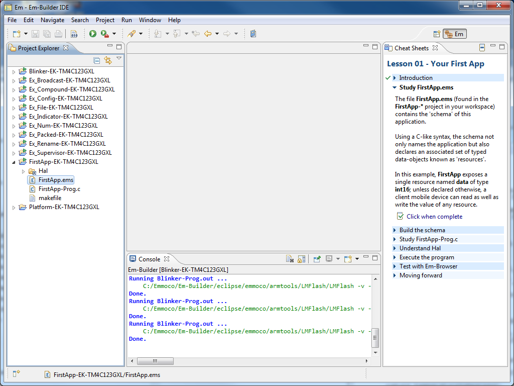
b) finished most of your schema with FirstApp, and made stubs for the callbacks
c) the schematic
d) hopefully a reference design close to your application. I'm using Tiva.

Because this is my first project using the Anaren BLE module, I routed all my module connections to the same signals as those used on the Anaren example that uses the TI TM4C123GXL LaunchPad and BoosterPack. This makes porting a little easier.

I recommend getting your schema and callback functions written while in the Em-Builder environment. Changing the schema after you move stuff over is a pain.

I like to start with the Hardware Abstraction Layer because that's the lowest level, and once it is done the rest should be fairly straightforward. Start by creating a new directory called Hal. In it create two blank files, Hal.h and Hal.c. First, copy and paste over the contents of the FirstApp Hal.h file. Save it and compile. Be sure that you don't have errors. My general approach is to go step by step, copying over stuff and compiling as we go. That way we can solve problems early instead of getting to the end and discovering a huge pile of problems to wade through.
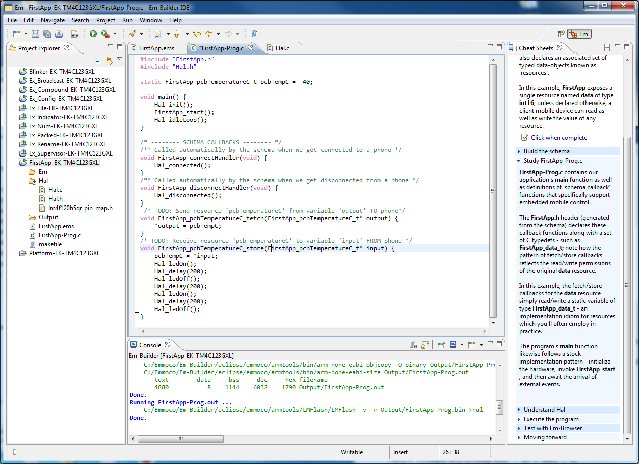
Porting Hal.c

I have Hal.c open in Em-Builder, and an empty file in my IDE named Hal.c. I've already copied over Hal.h. Now, to port Hal.c we're going to go step by step: start from the top of the file, copying over a little, modifying it as appropriate, and compiling.

#includes

First, copy over all the includes. The original Hal.c had two files:
#include "lm4f120h5qr_pin_map.h"
#include "inc/lm4f120h5qr.h"
... that can be replaced with the simpler driverlib one:
#include "driverlib/pin_map.h"
Now it should work better.

#defines

There are a couple of #defines that are rather perplexing. To clarify:
EAP_RX_ACK_PIN - this is an input to the module, and an output from the MCU
EAP_TX_ACK_PIN - this is an output from the module, and an input to the MCU
Next you'll see the LED stuff. I ported over the LED_PIN and CONNECTED_LED stuff but I commented out the BLUE_LED stuff. I also left out the BUTTON_PIN and DEBUG1_PIN and DEBUG2_PIN stuff. One thing that isn't self-explanatory: the #define MSEC_CYCLES is the number of cycles in a MSEC, so if your clock frequency is 50MHz, this would be equal to 50000.

Functions

I did not port over the debug functions Hal_debugOn, Hal_debugOff, Hal_debugPulse.

The Hal_Init() function is a big chunk of code, and should be done very carefully. Since I already have a hal_init function for the rest of the application, I renamed this BLE_Hal_init() so that it's clearer. I commented out a lot of the initialization stuff, but be sure to leave in the code that initializes the EAP TX & RX pins:
   SysCtlPeripheralEnable(SYSCTL_PERIPH_UART1);
   /* These are the module's special flow-control functions */

   GPIOPinTypeGPIOOutput(EAP_RX_ACK_PORT, EAP_RX_ACK_PIN);
   GPIOPinTypeGPIOInput(EAP_TX_ACK_PORT, EAP_TX_ACK_PIN);
    IntEnable(INT_GPIOA);
    GPIOIntEnable(EAP_TX_ACK_PORT, EAP_TX_ACK_PIN);

Also include the UART1 initialization, or whatever UART initialization you need. Be sure that it's configured properly.

The last line of their Hal_init function won't allow us to compile. Temporarily comment it out; we'll come back to that later.
//FIXME: update this once the rest is working
//handlerTab[DISPATCH_HANDLER_ID] = Em_Message_dispatch;
The FIXME tag will get automatically added to our list of tasks. This can be seen by adding the Tasks view. To do so navigate to: View : Other : General : Tasks and it should appear next to your problems tab.

With that you should be able to compile the entire Hal.c file.

Event Handling

We're handling event handling a little differently. The Hal.c file has a function:
void Hal_idleLoop(void)
But we're doing it differently, so temporarily we skip over this.

LED Functions

Port the Hal_ledOn, off, read, toggle functions next. If you set up your #defines then you should just be able to copy/paste these functions.

Timer Function

The next function is a little funky:
void Hal_tickStart(uint16_t msecs, void (*handler)(void))
The two parameters are:
  • msecs - the number of milliseconds before the timer expires
  • handler - the function that will be called when the timer expires.
This works in conjunction with Hal_timerIsr(void) which is called by the timer when it expires. The first line in the function:
handlerTab[TICK_HANDLER_ID] = handler;
adds an entry to the event handler table that should be called when the timer expiry event is processed. For now I'm commenting it out so that I can complete the port of the rest of the file.

SRT-HAL Interface

I think the "SRT" refers to the module. I had to do a little bit of googling to find that it means "Schema Runtime" which is as self-explanatory as "SRT". Or not. At any rate, these functions are the ones that handle the serial communication. Here you can see the funky communications protocol that the module uses. When I copied these functions over, the compiler didn't like that the Em_Hal_reset function used Em_Hal_unlock before it was declared, so I moved Em_Hal_unlock above the Em_Hal_reset function. Then Em_Hal_startSend didn't like how Em_Message_startTx was used because I haven't yet included the other Emmoco files.

Interrupt Service Routines

The ISRs are short and to the point which is nice. I did not copy over the Hal_buttonIsr function since I have my own. The rest of these functions form the real meat and potatoes of the module interface. This includes the serial receive ISR as well as the ISR for the handshake from the module, Hal_txAckIsr. When I added these, it became clear that I needed to import the Emmoco files now.

Adding the Emmoco Files

Now that we have a compiling Hal file, lets import the Emmoco files. I simply copied over the Em directory from my FirstApp to my project directory. The first thing that I did was add in the line at the top of my Hal.c file:
#include "Em_Message.h"
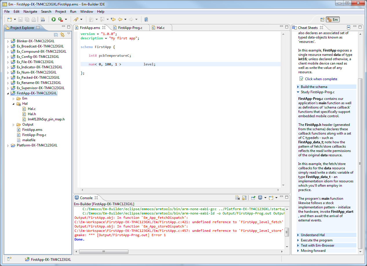
and tried to compile. Unfortunately it didn't work; the error
cannot open source file "Em_Message.h"
was displayed. Temporarily I fixed this by changing that line to:
#include "../Em/Em_Message.h"
But this is a hack.

Fixing the Interrupt Service Routines

When I ported the ISRs, there were a number of errors; some from the event handling, and one from an old Stellaris function that was used:
GPIOPinIntClear(EAP_TX_ACK_PORT, EAP_TX_ACK_PIN);
This has been replaced with:
GPIOIntClear(EAP_TX_ACK_PORT, EAP_TX_ACK_PIN);

Should be able to compile now

Following the steps outlined above (and commenting out the few pieces of code) you should be able to compile now.

Copy over the Application Logic

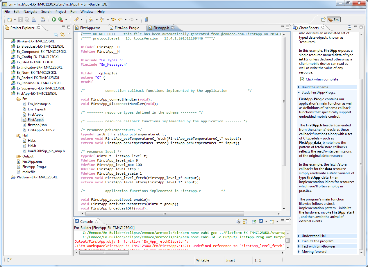
Now, in your main.c file (or whatever file holds your application), add the folowing line:
#include "Em/FirstApp.h"
And compile again. You shouldn't have any errors.

Over in Em-Browser, open your FirstApp-Prog.c file. We will be copying over some variables and functions from here. First, copy over the variables that are used:
static FirstApp_psuTemperatureC_t psuTempC = 10;
static FirstApp_pcbTemperatureC_t pcbTempC = 10;
static FirstApp_level_t intensity = 10;
static FirstApp_colorTemperature_t colorTemperature = 5600;
static FirstApp_command_t powerState = FirstApp_TURN_OFF;

Also, be sure to copy over the connectHandler and disconnectHandler functions; it turns out that the schema requires them.

Fix the Issues from Before

 Previously we commented out some code. Now, go back in and uncomment each part, and be sure it compiles. Add the start() method - the last three lines of your main application should be something like below:
/* The Hal_init() function for BLE stuff */
    BLE_Hal_init();
/* Initialize the BLE module */
    FirstApp_start();

/* The event handler that never exits */
    eventHandler();

Add Interrupt Vectors

The Tiva line of microcontrollers uses a very cool interrupt vector table to tell the processor which function to call for a given interrupt. Open the startup code file that you're using (mine is startup_ccs.c) and add the following interrupt functions, replacing IntDefaultHandler with the name of the function.
    Hal_txAckIsr,                           // GPIO Port A
    Hal_rxIsr,                              // UART1 Rx and Tx
    Hal_timerIsr,                           // Timer 0 subtimer A

Troubleshooting

After I was able to compile the code it didn't work. So, to troubleshooting we go. First, double check your schematic connections, as far as what is an input and what is an output. Next hook up a logic analyzer and observe, and compare to the reference traces:
http://wiki.em-hub.com/display/ED/Sample+Logic+Analyzer+Trace
When I started, I wasn't seeing the RX_ACK pulses after each byte received from the module. Doing a bit of troubleshooting, I found that the uart receive interrupt was not properly configured.


Wednesday, March 4, 2015

Fiducials in Altium

In Printed Circuit Board design, Fiducial marks are used to align the pick and place machine with the PCB. A fiducial requires a circular area free of silkscreen and solderpaste, and in the middle of that area is a smaller circle exposing the top metal of the PCB.

Creating these in Altium with keepouts can be problematic because it will create a keepout on both layers when typically you only want the keepout on the same layer as the fiducial.

I recently saw a great solution for this: do it with a clearance rule. Create a Clearance design rule named "FiducialClearance" (or whatever you want to name it) that specifies the 26mil clearance needed and is limited to just your fiducials. Create a new rule with the following:
HasFootprint('Fiducial-40mil')
Obviously, replace 'Fiducial-40mil' with the name of your fiducial footprint.


Finally change the priority of the "FiducialClearance" rule so that Priority=1.


Thursday, October 16, 2014

The Difference Between an Amateur Engineer and a Professional Engineer

An amateur grabs any old part from the parts bin and puts it into the board. A professional only uses parts that he has a valid part number for, since it will need to go into documentation somewhere.
An amateur assembles boards themselves. A professional only hand-builds if it will save money.
An amateur stores board revisions in zip files. A professional uses version control (like SVN).
An amateur doesn't pay attention to ESD when reworking boards. A professional uses proper grounding & wrist strap.
An amateur tries to solve all the problems himself. A professional coerces the manufacturer to help. :)
An amateur tests whether a design works. A professional tests how well the design works.
An amateur cares about the cost of the software tool. A professional cares about the productivity of the tool.
An amateur asks a question on a forum without RTFM. A professional asks a question on a forum after RTFM, usually when the documentation contradicts itself. :)
An amateur doesn't care about software licensing. A professional can tell you when you can use GPL code vs. LGPL vs. BSD license.

Friday, September 26, 2014

Demystifying Decoupling Capacitor Placement

Digital ICs require decoupling capacitors, to absorb the small current spikes from the switching behavior of the IC. Most of what we know about decoupling capacitor layout is "conventional wisdom", such as:

1. Need a variety of capacitance values to decouple a wide frequency range
2. Many capacitors of one value is better than many values
3. Place caps close to ICs
4. Location doesn't matter
5. Spread caps across the entire board

Most of our conventional wisdom is based on guidelines instead of empirical data.

I found an excellent presentation which explains proper decoupling capacitor placement:
https://ewh.ieee.org/r3/enc/emcs/archive/2012-10-10b_DecouplingMyths.pdf

Friday, August 1, 2014

Using Texas Instruments Tiva Microcontroller Temperature Sensor

The Tiva line of processors from Texas Instruments has an internal temperature sensor. Code to do this is below. To use this,
  1. Call halTemperatureSensorInit() to initialize the sensor and ADC. Only needs to be done once.
  2. Call halGetTemperature() to get the temperature in Celsius
  3. Optionally, call halConvertTemperatureFromCtoF to convert it to Fahrenheit
Example code is below.

/**
* Tiva Microcontroller Internal Temperature Utility Functions
*
* @section license License
* This work is PUBLIC DOMAIN
*
* YOU FURTHER ACKNOWLEDGE AND AGREE THAT THE SOFTWARE AND DOCUMENTATION ARE PROVIDED “AS IS”
* WITHOUT WARRANTY OF ANY KIND, EITHER EXPRESS OR IMPLIED, INCLUDING WITHOUT LIMITATION, ANY
* WARRANTY OF MERCHANTABILITY, TITLE, NON-INFRINGEMENT AND FITNESS FOR A PARTICULAR PURPOSE. IN NO
* EVENT SHALL  TESLA CONTROLS BE LIABLE OR OBLIGATED UNDER CONTRACT, NEGLIGENCE,
* STRICT LIABILITY, CONTRIBUTION, BREACH OF WARRANTY, OR OTHER LEGAL EQUITABLE THEORY ANY DIRECT OR
* INDIRECT DAMAGES OR EXPENSE INCLUDING BUT NOT LIMITED TO ANY INCIDENTAL, SPECIAL, INDIRECT,
* PUNITIVE OR CONSEQUENTIAL DAMAGES, LOST PROFITS OR LOST DATA, COST OF PROCUREMENT OF SUBSTITUTE
* GOODS, TECHNOLOGY, SERVICES, OR ANY CLAIMS BY THIRD PARTIES (INCLUDING BUT NOT LIMITED TO ANY
* DEFENSE THEREOF), OR OTHER SIMILAR COSTS.
*/

/**
 * Initialize the ADC for use by the temperature sensor.
 * @see TivaWare/examples/peripherals/adc/temperature_sensor.c
 * @post temperature sensor can be read with halGetTemperature()
 */
static void halTemperatureSensorInit()
{
    /** Enable the ADC */
    SysCtlPeripheralEnable(SYSCTL_PERIPH_ADC0);

#define ADC_SEQUENCE    3
#define ADC_STEP        0

    /* Enable sample sequence 3 with a processor signal trigger.
     * Sequence 3 will do a single sample when the processor sends a signal to start the conversion. */
    ADCSequenceConfigure(ADC0_BASE, ADC_SEQUENCE, ADC_TRIGGER_PROCESSOR, 0);

    /* Configure step 0 on sequence 3:
     * - Sample the temperature sensor (ADC_CTL_TS) in single-ended mode (default)
     * - Configure the interrupt flag (ADC_CTL_IE) to be set when the sample is done
     * - Tell the ADC logic that this is the last conversion on sequence 3 (ADC_CTL_END). */
    ADCSequenceStepConfigure(ADC0_BASE, ADC_SEQUENCE, ADC_STEP, ADC_CTL_TS | ADC_CTL_IE | ADC_CTL_END);

    /* Enable the ADC Sequence we're using */
    ADCSequenceEnable(ADC0_BASE, ADC_SEQUENCE);

    /* Clear the interrupt status flag. This is done to make sure the interrupt flag is cleared before we sample. */
    ADCIntClear(ADC0_BASE, ADC_SEQUENCE);
}


/**
 * Read the processor's internal temperature sensor. Accuracy is +/-5C
 * @pre halTemperatureSensorInit() was called to initialize the ADC
 * @return temperature of processor in degrees Celsius
 * @note to convert: VTSENS = 2.7 - ((TEMP + 55) / 75)
 */
int32_t halGetTemperature()
{
    /* This array is used for storing the data read from the ADC FIFO. It must be as large as the
    FIFO for the sequencer in use.  This example uses sequence 3 which has a FIFO depth of 1. */
    uint32_t ulADC0_Value[1];

    /* Our output value */
    int32_t temperatureInDegreesC;

    /* Manually Trigger the ADC conversion */
    ADCProcessorTrigger(ADC0_BASE, 3);

    /* Wait for conversion to be completed */
    while(!ADCIntStatus(ADC0_BASE, 3, false))
    {
    }

    /* Clear the ADC interrupt flag. */
    ADCIntClear(ADC0_BASE, 3);

    /* Read ADC Value. */
    ADCSequenceDataGet(ADC0_BASE, 3, ulADC0_Value);

    //UARTprintf("ADC Value = %u\n", ulADC0_Value[0]);

    /* Reference voltage of 3.3V, in mV.  */
#define REFERENCE_VOLTAGE_MV                (3300l)

    /* ADC is 12 bit resolution */
#define NUMBER_OF_STEPS_12_BIT_RESOLUTION   (4096l)

    /* The voltage from the ADC, in millivolts */
    uint32_t adcMv = (uint32_t) ((ulADC0_Value[0] * REFERENCE_VOLTAGE_MV) / NUMBER_OF_STEPS_12_BIT_RESOLUTION);

    /* Use non-calibrated conversion provided in the data sheet. Divide last to avoid dropout. */
    temperatureInDegreesC = (147500l - 75l * adcMv) / 1000;

    return temperatureInDegreesC;
}


/**
 * Utility function to convert a celsius temperature to fahrenheit.
 * @param temperatureInDegreesC the temp in C
 * @return the temp in F
 */
int32_t halConvertTemperatureFromCtoF(int32_t temperatureInDegreesC)
{
    return ((temperatureInDegreesC * 9) + 160) / 5;
}

Thursday, May 8, 2014

The Main Event - A Simple Event Handler for Microcontrollers

Every application has some type of event handler. Typically, an interrupt will occur, and the interrupt service routine (ISR) will then set a flag, and then the ISR will exit to return to the normal application. This approach is used to minimize the time spent in the ISR. Next, in the main application, the event flags are read, and if any were set then the application processes each event.

I've been looking through the Anaren Bluetooth Low Energy software lately, and I saw this rather cool event handler. It uses a table of function pointers that are the functions to be called when the event occurs.

The Event Handler Functions

We will create a typedef for our function pointer. All functions in our Event Handler Table need to be this type.
/* Typedef for the event handler functions that will go into our table */
typedef void (*Hal_Handler)(void);

Next, for convenience we also create a type for the event flag bitmask. For speed, make this the same as the processor's data size.
/* The type of integer that we will use for our event bitflag. uint32 = 32 possible events */
typedef uint32_t EventFlags;

We also create the global variable that will be the bitflag of any events that get set.
/* Bitflag of the events that need to be processed */
static volatile EventFlags handlerEvents = 0;

To complete the initialization, we define a few events, and create our event handler table.
#define NUM_HANDLERS 3
#define BUTTON_HANDLER_ID      0
#define TICK_HANDLER_ID        1
#define DISPATCH_HANDLER_ID    2

#define KNOB_INCREMENT_HANDLER_ID  3
#define KNOB_DECREMENT_HANDLER_ID  4

/* Table of handler function pointers */
static Event_Handler handlerTable[NUM_HANDLERS];

This table will contain function pointers for the function that gets called when the corresponding event gets called. For example, when the knob gets rotated clockwise, its ISR will set bit #3 in the handlerEvents function. Then the main loop will call the function that is located at handlerTable[3].

We initialize our list by adding event handlers to the event handler table using the method below:
 int addEventHandler(uint8_t index, Event_Handler handler)
 {
     if (index > NUM_HANDLERS)
     {
         return -1;
     }
     handlerTable[index] = handler;
     return 0;
 }

We then call this in our main() function, which we'll explain in a bit.

Set a flag when an event occurs

When an event happens, in the ISR we need to set the bitflag that corresponds to that event. This is done in the postEvent() method as shown below. This bitflag will be read later in our main event handling loop. For safety, we disable interrupts while we are modifying the handlerEvents variable.
/** Set the corresponding bitflag for the eventId */
void postEvent(uint8_t handlerId)
{
    //Note: you should check that handlerId < NUM_HANDLERS here
    IntMasterDisable();
    handlerEvents |= 1 << handlerId;
    IntMasterEnable();
}

In the ISRs, you will need to add a call to postEvent. For example, in a button ISR, add:
postEvent(BUTTON_HANDLER_ID);

Configuring The Actions

When the bitflag for an event gets set, we want the event handler to do something. It does so by calling a function pointer that points to the function that we want to get called when that event happens. For example, when a button is pressed we just want to tell the user. Same for knob, as shown below:
void buttonHandler(void)
{
    printf("Button Pressed!\r\n");
}
void knobIncrementHandler(void)
{
    printf("Knob Up!\r\n");
}
void knobDecrementHandler(void)
{
    printf("Knob Down!\r\n");
}

Now, we need these in the Event Table so in main() we add them with the function we created earlier:

    addEventHandler(BUTTON_HANDLER_ID, buttonHandler);
    addEventHandler(KNOB_INCREMENT_HANDLER_ID, knobIncrementHandler);
    addEventHandler(KNOB_DECREMENT_HANDLER_ID, knobDecrementHandler);

Now we've configured the event setting, and the event processing, so now we can implement the main event handler.

The Main Event (handler)

The Main Event Handler is fairly simple. It continually loops, and processes any events that were set by postEvent(). If a bitflag was set, then it calls the corresponding function pointer.
void eventHandler(void)
{
    IntMasterEnable();
    for (;;)
    {
        /* First, disable interrupts so we don't get messed up while we are reading events */
        IntMasterDisable();

        /* While interrupts are disabled, copy the current list of events that need to be processed */
        EventFlags events = handlerEvents;

        /* ... and clear the master bitflag of events */
        handlerEvents = 0;

        /* Now, process any events that need to be processed */
        if (events)
        {   // dispatch all current events
            IntMasterEnable();     // Enable interrupts - note that we do this before calling each handler function
            /* mask will be the bitflag that we use to check the events bitflag. Starts at 0x1, then 0x2, 0x4, 0x8 etc. */
            uint16_t mask;
            /* The numeric index of the event - 0 through 31 */
            uint8_t id;
            /** Iterate through all possible events */
            for (id = 0, mask = 0x1; id < NUM_HANDLERS; id++, mask <<= 1)
            {
                if ((events & mask) && handlerTable[id]) // If we need to process the event
                {                                      // AND there is an event handler for it
                    handlerTable[id]();                  // ... Then process the event
                }
            }
        } else {          // No events to handle, so wait for more
            /* If using a battery powered device, you could go back to sleep here. Just be sure to enable interrupts! */
            IntMasterEnable();        // Enable Interrupts
        }
    }
}


Friday, May 2, 2014

Using Bluetooth Low Energy to Do Something


In the previous post we looked at how to get up and running with Bluetooth Low Energy. Now we're going to do something useful. This section assumes that you have completed the previous tutorial successfully.

Load on-line Help

First, we want to load the on-line help for the FirstApp example. Open Em-Builder and select Help > Em-Builder > Primer Contents and you'll see a number of lessons available:
 Select "Lesson 01 - Your First App" and the workspace will change to load the on-line help:

Run Unmodified FirstApp

Just like you did for Blinker, now right-click on the FirstApp project in the left hand column and select "Run Em-Builder Example". If you had an error, be sure that your development board is attached, and try the Em-blinker example too. Now open Em-Browser on your iPhone and connect to your development board. You should be able to read and write a variable with the unoriginal name of "data". Fun.

Customizing FirstApp

The first thing that we're going to do to get our feet wet with the Emmoco software is to do something very simple: change the name of the "data" variable to "pcbTemperature". This will give us a good exposure to what Emmoco uses to communicate. Make the change in the schema, FirstApp.ems.


 If you try to build it, then you will get an error, complaining of an unknown type name.

Now in the schema (FirstApp.ems) change the name of the variable "data". This will cause the build to fail, because we need to change all the other variables. If you go to FirstApp.h then you can see declarations of the new typedef and functions.
Now, make these changes to FirstApp.c
Now that we've renamed the variables, we should be able to build successfully. Run the example (Right-click on project and select "Run Em-Builder Example") and it will be loaded on the development board. Using Em-Browser you should be able to read and write a resource named pcbTemperature.

Do Something When We Receive a New Value

Ok, now we're rolling.

Now, just for fun, we modify the function pcbTemperatureC_store() as shown below to blink LED twice whenever we get a new value.
Now, in Em-Browser, write a value to pcbTemperature and you'll see the LED blink twice. Cool! Too bad we don't have printf() here though; it would be nice to be able to see it.

Adding Another Variable

Now we want to add another variable. I looked through the schema examples and saw that there's a 'num' type where you can set the range and interval. This is useful so that the phone application will only send us valid values. We want to control a light, so we add a variable, called 'level'. This can vary between 0% (totally off) and 100% (totally on), in steps of 1 percent each.
Now right click on the project and select"Build Project". It will report a few errors but more importantly it will automatically generate the typedefs and function declarations that we need. This will make our lives easier.
Here we can see that the Emmoco framework created a bunch of new stuff for us, including the following.
The min, max, step, and scale values are there because in the schema we defined our variable as a number with range of 0 to 100 and in steps of 1. We can copy/paste the function declarations into our application to make life easier. Now we need to add these to our application.

In FirstApp-Prog.c, add a variable:
static FirstApp_level_t intensity = 10;
Also add two new functions:
/* Send resource TO phone */
void FirstApp_level_fetch(FirstApp_level_t* output)
{
    *output = intensity;
}

/* Receive new value FROM phone */
void FirstApp_level_store(FirstApp_level_t* input)
{
    intensity = *input;
}

Run the Example

Now, try building again - 'Run Em-Builder Example'. You shouldn't have any errors.
Now open Em-Browser on the iPhone. You can now see that we have a new resource, called Level, and we can write to it and read it.
Clicking on 'level' shows us more information about it. Note that if you try to write a level above 100 then it will be limited to 100.


Conclusion

In this tutorial we demonstrated how to modify one of their examples to do something useful and how to add another variable.


Get Started with Bluetooth Low Energy

This tutorial will show you how to develop an application with Bluetooth Low Energy and do something useful. Going through all the steps in this post will take between 30-60 minutes, depending on if you run into any issues. Bluetooth Low Energy (aka BLE) is all the rage right now, and rightfully so, as it is an easy to use low power RF communications protocol. All the new iPhones and some Android phones incorporate a BLE radio, so you can now easily design RF peripherals to communicate with the iPhone.

I like to use a module for BLE because it is easier and less expensive for quantities less than 10k. For this post I'm trying out the Anaren BLE Module which is available on a Development kit from Digikey for $60. You will also need a Texas Instruments Launchpad. I'm using the TI Tiva Launchpad which available from Digikey for about $14. These are so cheap that I recommend buying two. Below is a picture of the Anaren Board mounted on the Tiva Development Board.
 For this tutorial, you will need:
  • Anaren BLE Development Kit
  • Mini-USB cable for above (comes with the kit)
  • Texas Instruments Tiva Launchpad
  • Micro-USB cable for above (comes with the kit)
  • iPhone, 4S or later to run phone examples
  • iPhone apps "Em-Blinker" & "Em-Browser", available for free from the App Store
  • Basic knowledge of C

Hardware Connections

First, mate the two boards as shown above. Next, connect the Tiva's "Debug" USB port to your computer. Be sure that the slider switch is in the "DEBUG" position. Finally connect the "Admin UART" USB port on the Anaren Board to your computer.

Get the Software

The Anaren module uses a framework from Emmoco to make development easier. Go to www.em-hub.com. You will need to create an account to be able to download the software. Click on the "Sign-Up" link. The access code that it wants is printed on a sticker on the Anaren board. It is on the black connector, on the far left of the above image. Enter that code and your other information. Next, click on the "Downloads" link and select v13, and then "Em-Builder IDE Container" for your operating system.

Install the Software

After it downloads, install the software. It will also install some drivers too. When you first start the application it will look rather empty, like below.
Now we'll follow along the instructions in the left pane. Select Help > Em-Builder > Em-Hub Credentials and enter the same username and password you used to create your account.

Update Development Board Firmware

Next, you'll connect to the board and update the firmware. The hardest part on this step is figuring out which serial port is used for the "UART-ADMIN" port. I tried each of them but figured out finally that it was COM75 on mine. If the application is showing an error, then one thing to try is to press the "MCU Reset SOC" button on the Anaren Board; that allowed the two devices to connect. This took me awhile to figure out.

Once you have updated the firmware, it will be happy:
If you want, you can also change the name of the device here. Call it "SHAMU" or whatever you would like as long as it's all upper case. Now we're done updating the module firmware. If you want, you can remove the USB cable from the "ADMIN UART" port now.

Get the Example Projects

Now we need to import some examples so that we can start playing with them. GO to File > Import > Em-Builder > Example Projects, and select EK-TM4C123GXL as shown below.


Now, the application should have a few example projects:

Running an Example Application

Now we are ready to do something useful. Be sure that the USB cable to the Tiva board is connected to your computer. Right-click on the "Blinker-EK-TM4C123GXL" example and select "Run Em-Builder Example". It should compile and build, as shown below.
Now, open the "Em-Blinker" application on your phone. It should look something like below:
It doesn't do anything yet, you need to tell it to connect to your board. Press the button in the upper right corner to select the board. Previously we named our board "SHAMU" so we select that one. On the Tiva board, the Red LED should illuminate to indicate that it is connected to a phone.
Now, press "Start" or "On" depending on your version of Em-Blinker, and you should now see the blue LED on the Tiva board blink.

Conclusion

In this tutorial we started from zero and ended with a phone connected to our embedded device. Next time we'll look at making our own application.

Wednesday, April 30, 2014

The Easy Way to Use Thermistors


 A Thermistor is a resistor that varies its values with temperature. These are fairly inexpensive and easy to use with a microcontroller that has an analog to digital converter (ADC). However, figuring out how to compute the exact temperature is not simple. Here I go through the process that I use. I call it "The Easy Way" because I use Excel and Word to do the heavy lifting for me.

There are two types of thermistors, Negative Temperature Coefficient (NTC) and Positive Temperature Coefficient (PTC). Simply, for NTC thermistors, the resistance goes DOWN when the temperature goes UP.

In a circuit, thermistors are typically half of a voltage divider. In our example, the top half of the voltage divider is a 10k Ohm, 1% fixed resistor, powered by Vref, 2.5V. The bottom half of the voltage divider is a 10k Ohm 3% NTC thermistor.

Step 1: Get the temperature to resistance table

The math to convert from temperature to resistance is quite complex, so the manufacturers publish a table containing the resistance to temperature values. For example, see this link.

Step 2: Get them into Excel

For the table in the previous link the values were in a PDF sheet. But we need them in Excel. If you have a lot of time on your hands then you can manually retype them all. But I'm lazy, so I did some creative cut/paste from the PDF file into a Notepad file. You need a table consisting of many rows, each row containing the Temperature (in C) and also the Resistance (in Ohms). In Excel I also added another column containing the temperature in degrees Fahrenheit. This is just for convenience and not used in any calculations. The equation to convert from C to F in excel is the following, assuming the value in C is in cell A24:
=CONVERT(A24, "C", "F")
Below we see what our table looks like after we have all our values. We only computed for the temperature range of 0C to 85C because that was our product requirements.

Step 3: Get your ADC working

Use an oscilloscope to measure the output voltage of the voltage divider, while also measuring with the ADC. This will help you calibrate your calculations. Be sure that you know the resolution of your ADC to get the corresponding maximum counts. For example, a 12 bit ADC has 4096 possible values. Obviously to be able to measure temperature you will need to measure the voltage output from the thermistor voltage divider.

Step 4: Math Time

First, a few definitions:
  • R1 = our "top" resistor, in our case the fixed 10kOhm value
  • Rt = the varying thermistor resistance
  • Vref = the voltage supply to the top of the voltage divider, in our case 2.5V
  • Vt = the output voltage of this voltage divider
The equation for the thermistor being on the BOTTOM leg of the voltage divider is:
Rt                    Vt
-------       =   ---------
(R1 +Rt)          Vref

This can be rearranged to:
Rt = R1 / ( ( Vref/Vt) - 1)
Now, test this with your circuit, and verify that you are seeing reasonable values.
Next, we need to convert this to ADC measurements. But first a couple more definitions:
  • ADC= the value we measure from the ADC, in "counts"
  • Resolution = The resolution of the ADC. In our case, this is 4096 because we have a 12-bit ADC.
The ADC equation is:
Vt = (ADC / Resolution) * Vref
We can substitute this into the previous equation to get our magic equation:
ADC = (4096) / ( (R1/Rt) + 1)

Step 5: Make a Table

We can use this equation to create a table in Excel that contains the following tuplets:
  • Temperature (in C)
  • Resistance (in Ohms)
  • ADC Measurement
Using the Microsoft Excel Equation shown below. This assumes that our other resistor is 10k ohms, and our ADC has 4096 counts of resolution. In this case the raw resistance value is in cell C22. We
=((4096)/((10000/C22)+1))
However, this will give us decimal values. We want to round this off, so we use the following:
=ROUND(((4096)/((10000/C22)+1)), 0)

Below shows the table with the ADC values added:

Step 5: Convert this into a C Array

Here's where our laziness comes into play. We're going to use Microsoft Word to convert the list of values into a C array. First, select only the ADC column, starting at the value for 0C. Paste this as plain text into a new Microsoft Word file. Be sure to paste as plain text.
Now we have a wonderful list of values. Next, use Word's find/replace option to replace the carriage return with a comma and a space, as shown below. Note the find string is "^p" without the quotes, and the replace string is ", " without the quotes.
This performs a bit of magic, turning our long list into something that's starting to look like an array:
Now, just wrap this with the variable definition and a comment explaining what it is, and we're done.

/** ADC values which correspond to temperature starting at 0C up to 85C*/
const uint16_t adcToTemperature[] = {3008, 2973, 2937, 2900, 2864, 2827, 2789, 2752,
2714, 2675, 2636, 2598, 2558, 2519, 2480, 2440, 2401, 2362, 2322, 2283, 2243, 2204,
2165, 2126, 2086, 2048, 2010, 1971, 1934, 1896, 1859, 1822, 1785, 1749, 1713, 1678,
1643, 1609, 1575, 1541, 1508, 1476, 1443, 1412, 1381, 1350, 1320, 1290, 1261, 1232,
1204, 1177, 1150, 1123, 1097, 1072, 1047, 1022, 998, 975, 952, 929, 907, 886, 865,
844, 824, 804, 785, 766, 748, 730, 712, 695, 679, 662, 646, 631, 616, 601, 587,
573, 559, 545, 532, 519};

Step 6: Get the Temperature for ADC Reading

We now have our array of values. To get the temperature we just iterate through this table, looking for the closest match. We're not doing any interpolation or anything fancy, just a straight look-up. If you need more accuracy then do something different.
/** Gets the temperature in degrees C for the specified ADC reading.
 * @param adc the reading from the ADC
 * @return the temperature in C, or ERROR_TEMPERATURE_NOT_FOUND if the value was not found.
 */
uint8_t getTemperatureForAdc(uint16_t adc)
{
#define ADC_RESOLUTION                        (4096)

    if (adc > ADC_RESOLUTION)
    {
        return ERROR_TEMPERATURE_NOT_FOUND;  //error - this should not happen
    }

    /* Now iterate through the table, looking for the nearest match */
    uint32_t iterator = 0;
    while (adc < adcToTemperature[iterator])
    {
        iterator++;
    }
    if (iterator == ADC_TO_TEMP_LOOKUP_TABLE_ROWS)
    {
        // We've gone through the entire table but haven't found a match
        return ERROR_TEMPERATURE_NOT_FOUND;  //error - this should not happen
    }
    return (iterator);   // The temperature, in degrees C
}

Conclusion

We now have an easy and fast way to get the temperature from the thermistor.